
A Continuous and Uniform-speed Electrode Foil Rewinding Device

A technology of electrode foil and speed, which is applied in the direction of circuits, capacitors, electrical components, etc., can solve the problems of large mechanical impact, damaged appearance, and large speed change, so as to reduce mechanical impact, avoid frequent starting, and reduce mechanical impact. small effect

Active Publication Date: 2015-10-28
XINJIANG XIBU HONGYUAN ELECTRONICS CO LTD
View PDF6 Cites 0 Cited by
  • Summary
  • Abstract
  • Description
  • Claims
  • Application Information

AI Technical Summary

Problems solved by technology

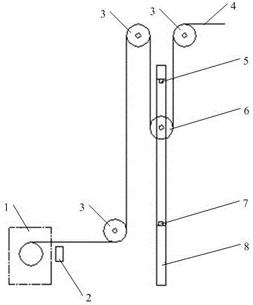
[0004] The foil collecting motor 1 of the above-mentioned electrode foil collecting device is frequently started, resulting in high energy consumption and large mechanical impact; the failure rate of the foil collecting motor 1 and the gear box is high; it affects the mechanical properties of the electrode foil 4 product
Since the speed of the foil take-up motor 1 is constant, the foil take-up speed changes with the diameter of the electrode foil roll during the winding process. The electrode foil roll changes from small to large, and the foil take-up speed changes from slow to fast. In practical applications, the electrode foil roll If the diameter is too large, the foil collection speed will be too fast. When it reaches the upper limit switch 5, it will not be able to stop in time. The foil deflection correction mechanism 2 cannot achieve the deflection correction function very well, so it affects the uniformity of the foil collection, and even makes the electrode foil wrinkle and damages the appearance
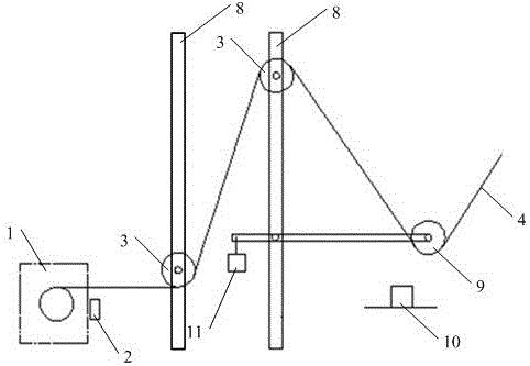
[0005] In the process of realizing the present invention, the inventor found that there are at least some defects in the prior art, such as large energy consumption, large mechanical impact force, high failure rate and poor deviation correction effect.

Method used


Image

  • A Continuous and Uniform-speed Electrode Foil Rewinding Device
  • A Continuous and Uniform-speed Electrode Foil Rewinding Device
  • A Continuous and Uniform-speed Electrode Foil Rewinding Device

Examples


Embodiment Construction

[0027] The preferred embodiments of the present invention will be described below in conjunction with the accompanying drawings. It should be understood that the preferred embodiments described here are only used to illustrate and explain the present invention, and are not intended to limit the present invention.

[0028] According to an embodiment of the present invention, an electrode foil retracting device capable of running continuously and at a constant speed is provided. Such as figure 2 and image 3 As shown, this embodiment includes a foil receiving motor 1 and a vertically arranged frame 8, which is arranged in cooperation with the frame 8, and is used for the transmission assembly for the electrode foil 4 to travel under the drive of the foil receiving motor 1, and is arranged in cooperation with the frame 8. The control mechanism between the foil motor 1 and the transmission assembly and used to control the foil collection speed of the foil collection motor 1 by d...


PUM


Abstract

The invention discloses a continuous constant-speed operation type electrode foil rolling device, comprising a foil rolling motor, a vertically-arranged rack, a transmission assembly arranged by being matched with the rack and driven by a foil rolling motor of an electrode foil, and a control mechanism which is arranged between the foil rolling motor and the transmission assembly in a matched manner, and is used for controlling a foil rolling speed of the foil rolling motor by detecting a position of the transmission assembly. With the adoption of the continuous constant-speed operation type electrode foil rolling device provided by the invention, the defects in the prior art of large energy consumption, large mechanical impact, high fault rate, poor deviation rectification effect can be overcome; and the advantages of small energy consumption, small mechanical impact, low fault rate and good deviation rectification effect can be realized.

Description

technical field [0001] The invention relates to the technical field of electrode foil production, in particular to a continuous and uniform-speed electrode foil collecting device. Background technique [0002] In the electrode foil production process, when the corrosion and formation process is completed, the electrode foil product should be wound neatly. In the conventional corrosion and formation process, the upper and lower limit switches are used to control the foil take-up motor. The purpose is to use the limit switch to control the foil take-up motor. The motor starts and stops to achieve neat winding of electrode foil products. [0003] figure 1 The electrode foil receiving device shown can be used in electrode foil corrosion and chemical formation production lines. Such as figure 1 As shown, the electrode foil receiving device includes a foil receiving motor 1, a foil receiving and deviation correction mechanism 2, a fixed roller 3, an electrode foil 4, an upper l...

Claims


Application Information

Patent Timeline
Patent Type & Authority Patents(China)
IPC IPC(8): H01G13/00H01B13/00
Inventor 乔正山钟志良张栓
Owner XINJIANG XIBU HONGYUAN ELECTRONICS CO LTD
Learn More