
Magnetic suspension wind driven generator

A wind turbine and magnetic levitation technology, which is applied in the direction of wind turbine components, wind engines, wind motor combinations, etc., can solve the problems of increased maintenance and repair costs, high use height, inconvenient installation, etc., and the height adjustment is simple and easy , The effect of flexible use of venues and flexible fixation methods

Active Publication Date: 2012-10-24
深圳市索阳新能源科技有限公司
View PDF7 Cites 10 Cited by
  • Summary
  • Abstract
  • Description
  • Claims
  • Application Information

AI Technical Summary

Problems solved by technology

[0005] The wind power generators in the prior art have the following disadvantages: 1. The cut-in wind speed is 3m / s, and the fan does not generate electricity when the wind speed is less than 2m, that is, it cannot generate electricity when the wind speed is low or the wind is light
2. Horizontal axis wind turbines have a choice of wind direction. During the power generation process, the wind direction needs to be constantly adjusted to achieve the best power generation effect. It is difficult to use different wind directions to obtain the best power generation effect.
3. Each wind wheel only drives one disc generator, so the conversion efficiency of wind energy is low
4. When the fan is running, the friction between the parts is large, the life of the generator is short, and it needs to be replaced frequently, which increases the cost of maintenance and repair
5. When the wind speed changes, the generator speed changes quickly and the torque fluctuates greatly
6. The use height is high, the installation is inconvenient, and the floor area is large
7. The fan fixing method is not flexible

Method used


Image

  • Magnetic suspension wind driven generator
  • Magnetic suspension wind driven generator

Examples


Embodiment Construction

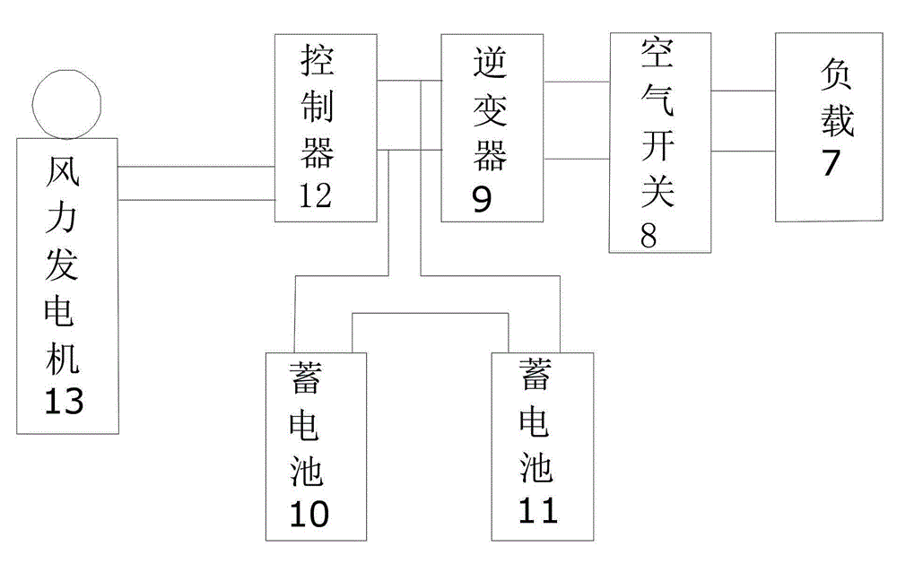
[0020] to combine figure 1 and figure 2 , which describes the specific implementation of the present invention in detail, but does not limit the claims in any way.

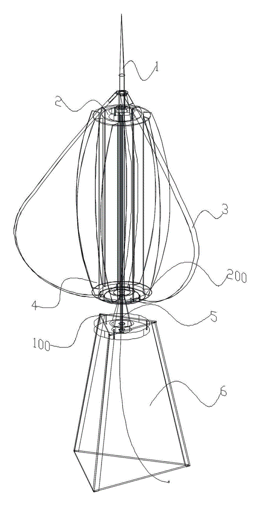
[0021] The maglev wind power generator of the present invention includes a fixed bracket 6, on which a bracket magnet 100 is arranged, a support shaft 5 is arranged in the bracket magnet 100, and a rotating wind wheel 4 is arranged on the outer periphery of the support shaft 5, so that The rotating wind wheel 4 is provided with wind wheel blades, and in this embodiment, there are 13 wind wheel blades. A wind wheel magnet 200 with the same polarity as the support magnet is arranged below the rotating wind wheel 4 , and a disc generator 2 is arranged between the rotating wind wheel 4 and the support shaft. There are two disk generators, which are respectively arranged above the rotating wind wheel 4 and below the rotating wind wheel 4 . A lightning arrester 1 is arranged above the support shaft 5 . In practice,...


PUM


Abstract

The invention relates to a magnetic suspension wind driven generator, and technically aims to provide the magnetic suspension wind driven generator, which can be used for normally generating power, has high wind power conversion efficiency, and is easy to disassemble and replace under the condition of low wind speed. The magnetic suspension wind driven generator comprises a fixed support, wherein a support magnet is arranged on the fixed support; a support shaft is arranged in the support magnet; a rotating wind wheel is arranged on the periphery of the support shaft and is provided with wind wheel blades; a wind wheel magnet opposite to the support magnet is arranged under the wind wheel, and the wind wheel magnet and the support magnet have the same magnetic pole; and a disk generator is arranged between the wind wheel and the supporting shaft. According to the magnetic suspension wind driven generator, the conversion efficiency of wind energy is improved by more than 50 percent, and the power generation cost of the wind driven generator can be greatly reduced. The magnetic suspension wind driven generator is applicable to a wind power generation field.

Description

[0001] technical field [0002] The invention relates to a wind power generator, more specifically, to a small-sized magnetic levitation wind power generator. Background technique [0003] At present, wind power generation, as a renewable and environmentally friendly energy source, has attracted more and more attention from countries all over the world. The potential of wind power generation is huge. The global wind energy is about 2.74×10⁹MW, of which the usable wind energy is 2×10⁷MW, which is 10 times larger than the total amount of water energy that can be developed and utilized on the earth. China's wind energy has great utilization potential and wide distribution. The wind energy reserves on land alone are about 253 million kilowatts. With the development of the global economy, the wind energy market has also developed rapidly. Since 2004, global wind power generation capacity has doubled, and between 2006 and 2007, global wind power generation capacity expanded b...

Claims


Application Information

Patent Timeline
Patent Type & Authority Applications(China)
IPC IPC(8): F03D9/00F03D3/06F03D11/00F03D9/25F03D13/20F03D80/30
CPCY02E10/74
Inventor 沈元仲沈亨春
Owner 深圳市索阳新能源科技有限公司
Learn More