
Sleeve gas collection device and method

A technology for collecting device and casing gas, which is used in earth-moving drilling, fluid production, wellbore/well components, etc., can solve problems such as impracticality, and achieve the effects of simple construction, reduced environmental pollution, and reduced waste of resources

Inactive Publication Date: 2012-10-24
刘庆敏
View PDF7 Cites 6 Cited by
  • Summary
  • Abstract
  • Description
  • Claims
  • Application Information

AI Technical Summary

Problems solved by technology

Therefore, the device is not practical in production

Method used


Image

  • Sleeve gas collection device and method
  • Sleeve gas collection device and method

Examples


Embodiment Construction

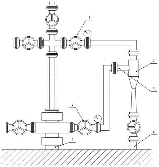
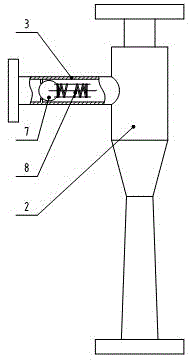
[0011] see figure 1 and figure 2 , figure 1 It is a schematic diagram of the installation of an embodiment of the casing gas collection device on the electric submersible pump well, figure 2 It is a structural diagram of an embodiment of the casing gas collection device. Install a jet pump 2 between the oil outlet valve 1 of the oil tree and the oil delivery pipeline 5, connect the suction pipe 3 and the casing valve 4 through the pipeline, install a one-way valve 7 in the suction pipe 3, and install a one-way valve in the one-way valve 7 Return spring 8, the fluid can only pass in the direction of the jet pump 2, and cannot pass in the opposite direction. When the oil well is pumped, the oil with a certain pressure and speed enters the jet pump 2, and a negative pressure is formed in the jet pump 2, the check valve 7 in the suction pipe 3 opens, and the natural gas in the casing 5 passes through the suction pipe 3 It is sucked into the jet pump 2, mixed with the oil in ...


PUM


Abstract

The invention discloses a sleeve gas collection device and method. The sleeve gas collection device consists of a jet pump and a check valve, and is characterized in that the jet pump is mounted between a Christmas tree oil outlet valve and an oil conveying pipeline; a gas suction pipe and a sleeve valve are connected through a pipeline; the check valve is arranged in the gas suction pipe; and the fluid can pass only toward the jet pump rather than the opposite direction. The device and method are simple to implement, and meet the technical requirements of the safe production of an oil field; the device is applied to a common pumping unit well or an electric submersible pump well without adding other equipment, the sleeve gas can be effectively collected, and the environmental pollution and resource waste are reduced; and moreover, after the pumping of an oil well is stopped, the oil in the oil conveying pipeline does not flow back to the sleeve.

Description

technical field [0001] The invention relates to a device and method for collecting oil well casing gas, in particular to a device and method for collecting oil well casing gas on the ground. Background technique [0002] Crude oil contains a considerable amount of dissolved natural gas. During the production process, these dissolved gases will gradually decompose in the form of gas to form free natural gas, which will accumulate in the annular space between the tubing and casing (hereinafter referred to as the casing annulus), commonly known as casing Gas. If the casing gas is not discharged, it will affect the normal production of the oil well; if it is directly discharged into the atmosphere, it will pollute the environment and cause a waste of resources. Chinese patent 200920146986.8 discloses a casing gas collection device for oil wells, which can suck the casing gas into the production pipeline. When the machine goes down, the liquid flow in the pipeline stops, and th...

Claims


Application Information

Patent Timeline
Patent Type & Authority Applications(China)
IPC IPC(8): E21B43/00
Inventor 王欣辉舒华文官鹏马波刘庆敏
Owner 刘庆敏
Learn More