Initial rainwater source catch basin
A technology of initial rainwater and interception wells, which is applied in the field of interception wells, can solve problems such as heavy pollution, and achieve the effects of reducing complexity, quantity, and pipe diameter
- Summary
- Abstract
- Description
- Claims
- Application Information
AI Technical Summary
Problems solved by technology
Method used
Image
Examples
Embodiment 1
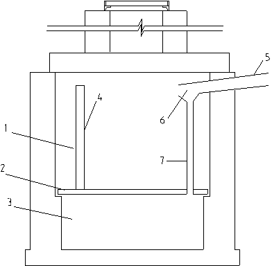
[0017] Example 1, see figure 1 and figure 2 , image 3 :
[0018] As can be seen from the figure, the intercepting well is mainly composed of a well cover 12, a well body 13, a vent pipe 4, a well neck 14, a ladder 15, an intermediate partition 2, and an initial rainwater intercepting pipe 7. The well body can be designed as a circle or a rectangle according to the needs, and it is divided into upper and lower wells 1 and 3 by the middle partition 2. The connection of the upper and lower layers of pipes and the access of branch pipes are based on the middle partition. Connect the sewage pipes and canals, the upper well 1 is connected to the rainwater pipes and canals, and a ventilation pipe 4 is provided on the middle partition to connect the upper and lower floors, so as to realize the normal ventilation and safe operation of the lower well. The top of the ventilation pipe should be higher than the design water depth of the upper well. In order to ensure the normal ventil...
Embodiment 2
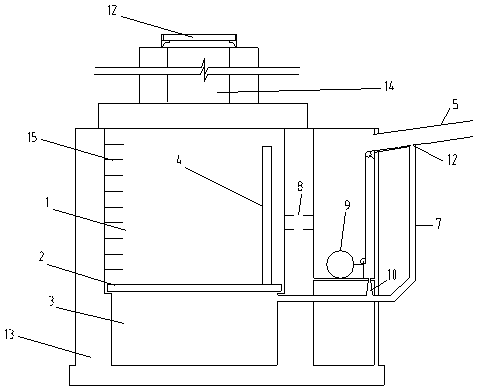
[0019] Example 2, see figure 2 and figure 1 , image 3 :
[0020] As shown in the figure, the basic form and composition of the interception well are the same as figure 1 The one shown is similar, but the difference is that the upper well space of the intercepting well is separated by a vertical wall into an overflow control room 16, and a float valve mechanism 9 (including a float valve and spring, etc.) is arranged in the control room. There is a clean rainwater overflow hole 8 connected to another part of the upper well at a certain height. The overflow hole can be normally open, or can be opened and closed by a float valve to realize the overflow of clean rainwater. flow to ensure safety. Moreover, a drain hole 10 is provided at the bottom of the upper layer of the interception well to be connected with the downhole layer, and the drain hole can be communicated with the interceptor pipe. This hole is used for the discharge of the bottom rainwater when the upper layer...
Embodiment 3
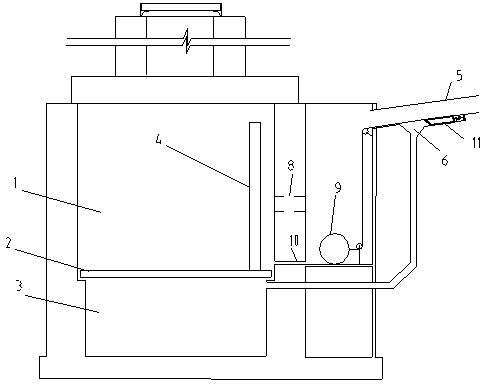
[0021] Example 3, see image 3 and figure 1 , figure 2 :
[0022] It can be seen from the figure that the interception well is in figure 2 On the basis of the intercepting well shown, the position of the discharge hole 10 is changed, and the discharge hole is opened on the vertical wall, directly leading to the lower layer well of the interception well. compared to figure 2 The interception well can realize that the discharge hole and the overflow hole are controlled by a float valve at the same time, and can make the flushing effect of the upper well better. In addition, an automatic opening and closing control device 11 is installed in the initial rainwater interception structure 6 at the top of the interception pipe to control the opening and closing of the interception pipe, so that the interception amount of the initial rainwater can be accurately controlled, and the interception pipe is closed later to make the rainwater clean in the middle and late stages It is ...
PUM
 Abstract
Description
Claims
Application Information
 - R&D Engineer
- R&D Manager
- IP Professional
- Industry Leading Data Capabilities
- Powerful AI technology
- Patent DNA Extraction
Browse by: Latest US Patents, China's latest patents, Technical Efficacy Thesaurus, Application Domain, Technology Topic, Popular Technical Reports.
© 2024 PatSnap. All rights reserved.Legal|Privacy policy|Modern Slavery Act Transparency Statement|Sitemap|About US| Contact US: help@patsnap.com


