Labelling device

A labeling and self-adhesive label technology, which is applied in the directions of transportation and packaging, sending objects, thin material processing, etc., to achieve the effect of good effect, simple structure and reliable operation

Active Publication Date: 2012-10-24
MAXIM SMART MFG CO LTD
View PDF12 Cites 11 Cited by
  • Summary
  • Abstract
  • Description
  • Claims
  • Application Information

AI Technical Summary

Problems solved by technology

[0004] At present, there is no automatic bonding equipment between the chip / pad and the backing paper

Method used


Image

  • Labelling device
  • Labelling device
  • Labelling device

Examples


Embodiment Construction

[0028] Below in conjunction with accompanying drawing, the present invention is described in further detail, so that those skilled in the art understand:

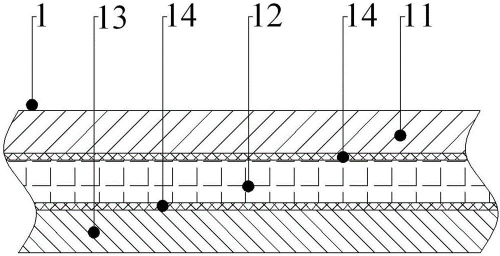
[0029] Such as Figure 1-6 As shown, the labels respectively represent: RFID electronic label 1, printing paper 11, RFID chip 12, backing paper 13, self-adhesive layer 14, liner 15, self-adhesive label paper tape 2, release paper tape 21, unwinding wheel 3. Tensioning device 4, driven roller 41, ring 411, set screw 4111, ring 412, set screw 4121, pressing mechanism 42, shaft 421, sleeve 422, pressing plate 423, pressing layer 424, tightening Screw 425, bolt 426, first guide roller 51, second guide roller 52, third guide roller 53, peeling plate 6, labeling roller 7, roller shaft 71, roller 72, winding wheel 8, flange 81, A base 9 , a guide plate 10 , a position detection device 110 , a controller 120 , and a driving mechanism 130 .

[0030] see figure 1 , the embodiment of the present invention proposes a compound device...


PUM


Abstract

The invention relates to the technical field of mechanical equipment, and in particular relates to a labelling device. The labelling device is applied to splicing among a chip, a liner and a body paper in an electronic tag; the liner/chip is provided with an adhesive sticker layer, and the liner and the chip are sequentially adhered to a banded release paper tape, thus a self-adhesion label band is formed. The labelling device disclosed by the invention comprises a base platform used for transporting the body paper, an unwinding wheel used for placing a roll formed by the self-adhesion label band, a winding wheel used for rewinding the release paper tape which is stripped from the chip/liner as well as a tension device for the transport path of the release paper tape and a stripping plate which are sequentially restricted and arranged between the unwinding wheel and the winding wheel. The labelling device disclosed by the invention realizes automatic combination between an RFID (radio frequency identification) chip/liner and the body paper in an RFID electronic label production process. Combination speed is rapid, effect is good, production efficiency is greatly improved, and the labelling device can coordinate with the existing production line; and the labelling device disclosed by the invention has the advantages of a simple structure, reliable operation, low cost and high reliability and is convenient for adjusting, can be applied to production of the RFID electronic labels in different specifications and has good practical value.

Description

technical field [0001] The invention relates to the technical field of mechanical equipment, in particular to a labeling device. Background technique [0002] see figure 1 , which is a structure of paper-encapsulated RFID electronic tags, including printed paper 11, RFID chip 12 and bottom paper 13 arranged in sequence from top to bottom, wherein between the printed paper 11 and RFID chip 12, the RFID chip 12 and the bottom paper The papers 13 are bonded to each other through the self-adhesive layer 14 . see figure 2 , which is figure 1 The improved structure of the paper package RFID electronic tag, the difference is that a liner 15 for protecting the RFID chip 12 is also provided between the RFID chip 12 and the backing paper 13, and the liner 15 is also connected with the self-adhesive layer 14. The RFID chip 12 and the backing paper 13 are bonded. [0003] The above two paper-encapsulated RFID electronic tag structures are widely used because of their low cost. In...

Claims


Application Information

Patent Timeline
Patent Type & Authority Applications(China)
IPC IPC(8): B65H37/04
Inventor 翟所强
Owner MAXIM SMART MFG CO LTD
Why Eureka
Try Eureka