Three-dimensional vacuum cupping device

A vacuum and three-dimensional technology, applied in the direction of suction equipment, etc., can solve the problems of difficult adjustment of movable plates and positioning blocks, easy abrasion of limbs, difficulty in getting in and out of rubber sleeves, etc., to achieve stable and reliable vacuum protection, good vacuum protection effect, and support Stable and reliable effect

Inactive Publication Date: 2012-10-24
刘玉海 +1
View PDF7 Cites 8 Cited by
  • Summary
  • Abstract
  • Description
  • Claims
  • Application Information

AI Technical Summary

Problems solved by technology

[0011] The first problem that the comparative document ⑥ exists is that the middle of "fixed baffle plate 6 is provided with the positioning block 7 of four movable plates 9 positions" is the affected limb, and the outer end is blocked by a rubber sleeve. It is difficult to adjust in the rubber sleeve; the second problem is that it is difficult for the limbs to get in and out of the rubber sleeve without being squeezed and pulled, which is easy to cause abrasions on the limbs, and it is even more difficult for the affected limbs, especially the injured and sick limbs; If the effect of air extraction and vacuum protection is good, after more than ten minutes of cupping treatment, the treated parts such as hands, feet, elbows and knees will be congested and swollen by about 20%, and there may even be many bleeding points or blisters. How to withdraw the cupping body and rubber sleeve? The third problem is that when the rubber sleeve enters and exits the limbs, hands, feet and other parts, it will be pulled unevenly and excessively, and it is easy to be damaged and cracked, making it unusable

Method used


Image

  • Three-dimensional vacuum cupping device
  • Three-dimensional vacuum cupping device
  • Three-dimensional vacuum cupping device

Examples


Embodiment Construction

[0047] Below in conjunction with accompanying drawing, the present invention is described in further detail:

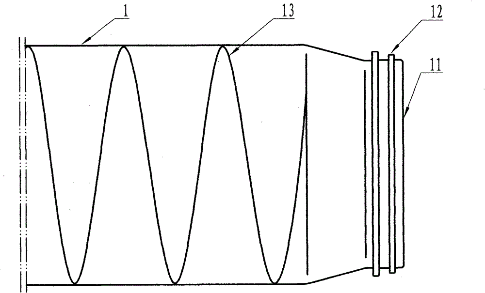
[0048] figure 1 It is a schematic diagram of the shell structure of the present invention: a hard shell 1 with one end open, a port 11 , a corrugated ring 12 , and corrugated ribs 13 .

[0049] figure 2 It is a semi-soft shell 1 with one or both ends open, a hard port 11, a convex ring 12, and a spring-like rib 13. The position of the spring rib can be set inside and outside the shell, or it can be injected into the semi-soft shell wall .

[0050] image 3 It is a hard shell 1 with openings at both ends or multi-ports and multi-sections. There are straight-through and shrinking ports 11 in the multi-section openings. There are reinforcing ribs 13 in the body mouth or middle, and the sections are connected by rubber sealing rings 14 between shells to form a vacuum airtight; or each section is air-sealed by O-shaped rubber polyurethane sealing rings 15, and the cl...


PUM


Abstract

The invention discloses a three-dimensional cupping type physical therapy device and aims at providing a three-dimensional cupping device which can achieve containing type vacuum sealing on the trunk and the limbs, enables the limbs to move in and out of a casing and a seal ring without being limited or scratched easily, is simple and convenient to use and enables the easily damaged part seal ring to be durable. The cupping device comprises the casing, the loop sleeve type seal ring, an air suction nozzle, a hose and a vacuum pump. A self-adaption aperture-changing support ring is arranged on the inner side of the loop sleeve type seal ring on the outer side of a port of the casing. The three-dimensional cupping device can be used for treating difficult and complicated diseases such as limb cold, arthralgia, hand and foot numbness, amyotrophy chap, diabetic feet at an early stage, blood vessel blockage stasis and vessel disappearance, and is also a novel device for safe and rapid postoperation physical therapy against injury caused by disasters and car accidents and sports wound and the like. The three-dimensional cupping device can have instant initial-stage curative effects and good long-term effects, does not cause positive and toxic and side effects of medicines or operation injury and can facilitate low-cost cure and health care physical therapy at hospital clinics or homes.

Description

technical field [0001] The invention relates to a cupping type physiotherapy device, in particular to a three-dimensional vacuum cupping appliance which mainly utilizes the principle of negative pressure to treat human diseases. Background technique [0002] In ancient times, China had already invented animal horn cupping devices. In the early Chinese medical book "Fifty-two Disease Prescriptions", which was written in the Spring and Autumn Period (770 BC to 476 BC) or the Spring and Autumn Period (about the fifth century BC), there are already records about the treatment of diseases with horn method ( See "General History of Chinese Medicine Ancient Volume" P63~112, "History of Ancient Chinese Science and Technology" P123). The original horn pots have successfully cured diseases and been passed down for thousands of years. In the vast land of China, cupping technology has been continuously developed for more than two thousand years in ancient, recent and modern times, and...

Claims


Application Information

Patent Timeline
Patent Type & Authority Applications(China)
IPC IPC(8): A61M1/00
Inventor 刘玉海刘霄纬
Owner 刘玉海
Why Eureka
Try Eureka