Touch panel module

A touch panel and module technology, applied in optics, instruments, electrical digital data processing, etc., can solve problems such as low yield, damage, and increased material cost

Inactive Publication Date: 2012-10-17
HANNSTAR DISPLAY CORPORATION
View PDF1 Cites 9 Cited by
  • Summary
  • Abstract
  • Description
  • Claims
  • Application Information

AI Technical Summary

Problems solved by technology

[0003] However, at present, the yield rate of the liquid crystal display module 93 and the touch panel 90 using optical glue is still low, and heavy tools are difficult.
During heavy work, the liquid crystal display module 93 and the touch panel 90 need to be separated, and the hardened optical adhesive is likely to cause damage to the liquid crystal display module 93 and the touch panel 90, especially damage to the upper polarizer of the liquid crystal display module 93.
This also increases the cost of materials for heavy work

Method used


Image

  • Touch panel module
  • Touch panel module
  • Touch panel module

Examples


Embodiment Construction

[0022] In order to make the above objects, features and advantages of the present invention more comprehensible, preferred embodiments of the present invention are exemplified below and described in detail in conjunction with the accompanying drawings. Furthermore, the directional terms mentioned in the present invention, such as "up", "down", "front", "back", "left", "right", "inside", "outside" or "side", etc., It is only for orientation with reference to the attached drawings. Therefore, the directional terms used are used to illustrate and understand the present invention, but not to limit the present invention.

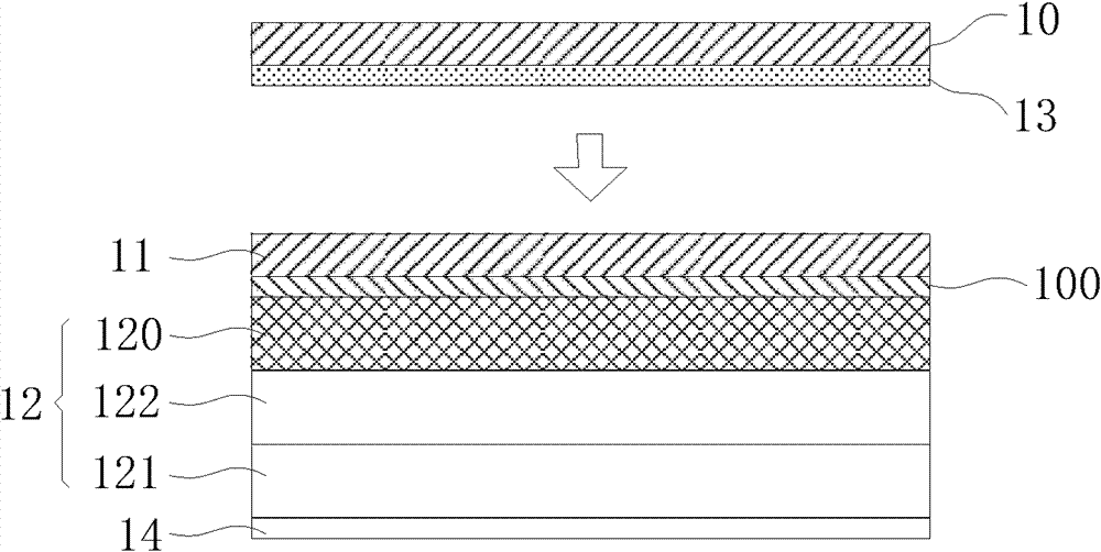
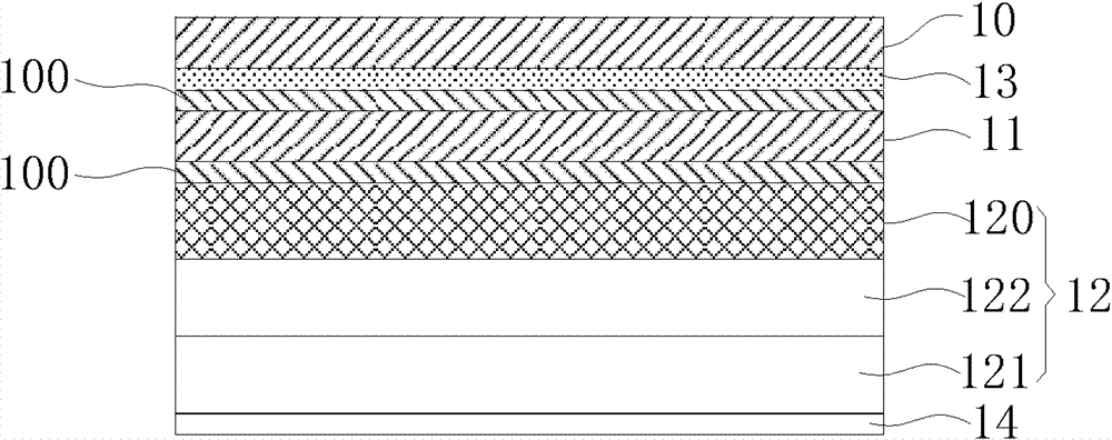
[0023] Please refer to figure 2 and image 3 as shown, figure 2 A schematic diagram showing a preferred embodiment of the touch panel module of the present invention before the combination of the protection sheet and the touch sensing structure, image 3 then figure 2 combination diagram. The touch panel module mainly includes a touch sensing structure 1...


PUM


Abstract

The invention discloses a touch panel module including a touch sensing structure, a protection piece, an upper polaroid and a liquid crystal box, wherein the protection piece is arranged at the top of the touch sensing structure through optical cement; the upper polaroid is arranged between the touch sensing structure and the protection piece; and the liquid crystal box is arranged at the bottom of the touch sensing structure. The touch panel module can prevent the upper polaroid from being damaged when the touch sensing structure and the liquid crystal box are attached and reworked, thus reducing material cost loss caused by attaching and reworking of the optical cement.

Description

technical field [0001] The present invention relates to a touch panel module, in particular to a touch panel module which can reduce the cost of optical adhesive lamination and rework. Background technique [0002] Please refer to figure 1 Shown is a combination diagram of an existing touch panel module. The existing touch panel module 9 (Touch Panel Module, TPM) mainly includes a touch panel 90 (Touch Panel) and a liquid crystal display module 93 (Liquid Crystal Module, LCM). Wherein the touch panel 90 includes a touch sensing structure 92 and a protection sheet 91, and the protection sheet 91 is attached to the touch sensing structure by optical glue 900 (or liquid optically clear adhesive) 92 on. The touch sensing structure 92 is also combined with the liquid crystal display module 93 through the optical adhesive 900 . [0003] However, currently, the yield rate of bonding the liquid crystal display module 93 and the touch panel 90 using optical glue is still low, and...

Claims


Application Information

Patent Timeline
Patent Type & Authority Applications(China)
IPC IPC(8): G06F3/041G02F1/1335G02F1/133
Inventor 曾建翔邱铭圣张克勤邓嘉峰
Owner HANNSTAR DISPLAY CORPORATION
Why Eureka
Try Eureka