Relevance model based infrared earth sensor measuring point optimal configuration method

A technology of earth sensor and correlation model, applied in the direction of integrated navigator, etc., can solve the problems of less measurement point configuration of earth sensor, difficult to achieve fault location, lack of optimal configuration of measurement points, etc., so as to improve on-orbit fault diagnosis. capacity, improved detectability, improved separability effects

Active Publication Date: 2012-10-17
BEIJING INST OF CONTROL ENG
View PDF2 Cites 9 Cited by
  • Summary
  • Abstract
  • Description
  • Claims
  • Application Information

AI Technical Summary

Problems solved by technology

However, the analysis of the measuring points of the earth sensor from the perspective of fault diagnosis shows that there are some problems in the configuration of the measuring points of the earth sensor, that is, there are very few measuring points of the earth sensor, and among many faults, the power state telemetry and The temperature telemetry of the detector only reflects very few faults, which is

Method used


Image

  • Relevance model based infrared earth sensor measuring point optimal configuration method
  • Relevance model based infrared earth sensor measuring point optimal configuration method
  • Relevance model based infrared earth sensor measuring point optimal configuration method

Examples


specific Embodiment approach

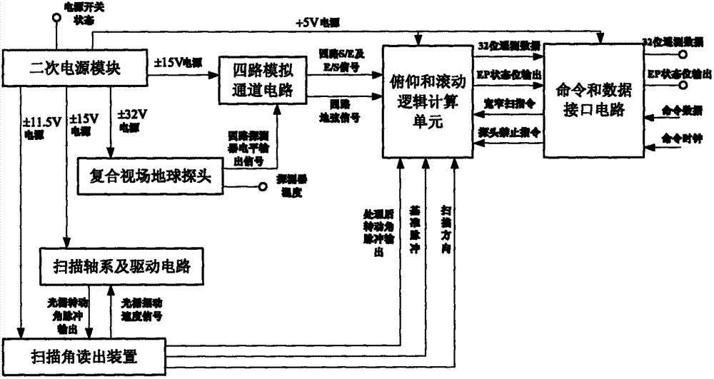
[0044] The infrared earth sensor is an attitude sensor that measures the pitch angle and roll angle relative to the center of the earth. It plays an important role in accurately entering the orbit and maintaining the attitude of the satellite. Its functional modules can be divided into a composite field of view earth probe and four analog channels. , Scan axis system and drive circuit, scan angle readout device, pitch and roll logic calculation unit, command and data interface circuit and secondary power supply, the functions of each functional module are shown in Table 1.

[0045] The optical system of the infrared earth sensor includes a compound field of view composed of 4 pencil-shaped beams. Under normal circumstances, with the swing of the scanning shaft system, these beams scan the horizon along the scanning path of 45° north and south latitude. The scanning path Including space segment and horizon segment. The four earth signals are respectively processed by the four a...

Embodiment approach

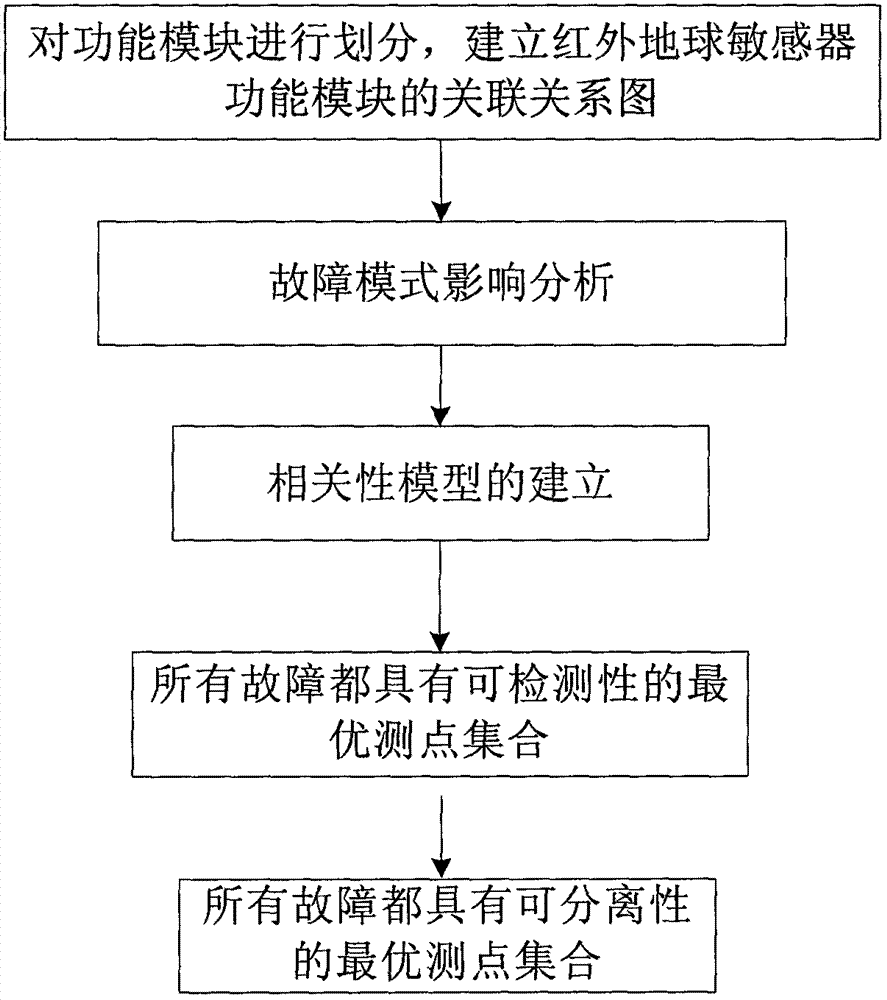
[0069] Step 4 is mainly based on the fault-state information correlation matrix to obtain the optimal set of measuring points that make all faults detectable. The basic steps are as follows:

[0070] (1) For the fault and state information correlation matrix, calculate the number of non-zero elements in the column where each state is located, and sort all states according to the descending method;

[0071] (2) Add the top state to the optimal measuring point set, and delete the row where the non-zero element is located in the column corresponding to the state;

[0072] (3) Repeat steps (1)-(2) until all rows are deleted.

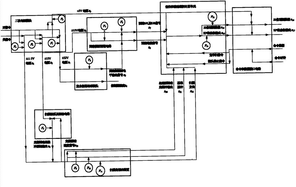
[0073] According to the above steps, the optimal measuring point to make all faults of the infrared earth sensor detectable is {s 14 ,s 15} and {s 16 ,s 17}.

[0074] The specific implementation of step (5):

[0075] Step (5) is mainly based on the correlation matrix of fault and state information to obtain the optimal set of measuring points that make...


PUM


Abstract

The invention discloses a relevance model based infrared earth sensor measuring point optimal configuration method. Firstly, an association graph of an infrared earth sensor's function modules is built. Then, aiming at various kinds of faults happened during on-orbit and test stages of the infrared earth sensor, its fault pattern set is determined. Based on the association graph of each function module, a multi-signal flow graph of the infrared earth sensor is acquired. Based on the multi-signal flow graph, a fault and state information incidence matrix of the infrared earth sensor is established. And based on the established fault and state information incidence matrix, an optimal measuring point set which endows all the faults with detectability and an optimal measuring point set which makes all the faults separable are acquired. According to the invention, based on the case that it is ensured that resource constraint is satisfied, many faults are detected and separated, and a basis for diagnosable design of a satellite control system is provided.

Description

technical field [0001] The invention relates to a correlation model-based method for optimizing the configuration of measuring points of an infrared earth sensor, and belongs to the technical field of aerospace fault diagnosis. Background technique [0002] The infrared earth sensor, as a sensor of the satellite control system, mainly obtains the attitude information of the satellite relative to the earth by means of optical means, and outputs the signal carrying this information after processing. It is a necessary means for the satellite to capture the earth and orient itself to the earth . At present, the measurable information of the infrared earth sensor obtained by AOCC mainly includes power state telemetry, detector temperature telemetry, EP state, and roll and pitch angle signals. To realize fault location, it is required that each measuring point can fully reflect the fault change, and realize fault diagnosis through different manifestations of the measuring points....

Claims


Application Information

Patent Timeline
IPC IPC(8): G01C21/24
Inventor 王南华刘文静刘成瑞何英姿刘新彦邢琰
Owner BEIJING INST OF CONTROL ENG
Why Eureka
Try Eureka