
Exhaust system for passenger car clutch

An exhaust system and clutch technology, which is applied in the exhaust system field of passenger car clutches, can solve the problems of heavy air bubble removal, poor clutch operation, oil leakage of clutch oil pipes, etc., and achieves wide application range, reduced work intensity, and tight seal good performance

Inactive Publication Date: 2012-10-17
ZHANGZHOU JINLONG BUS
View PDF0 Cites 0 Cited by
  • Summary
  • Abstract
  • Description
  • Claims
  • Application Information

AI Technical Summary

Problems solved by technology

Air bubbles will be generated in the clutch oil pipe, and the clutch will not work smoothly after the air bubbles are generated, and the workload of removing air bubbles is large, and the maintainability is not good
The clutch oil pipe needs to be disassembled when the original system is exhausted. After the oil pipe is disassembled many times, it will wear and tear, causing the clutch oil pipe to leak oil at the joint part.

Method used


Image

  • Exhaust system for passenger car clutch

Examples


Embodiment

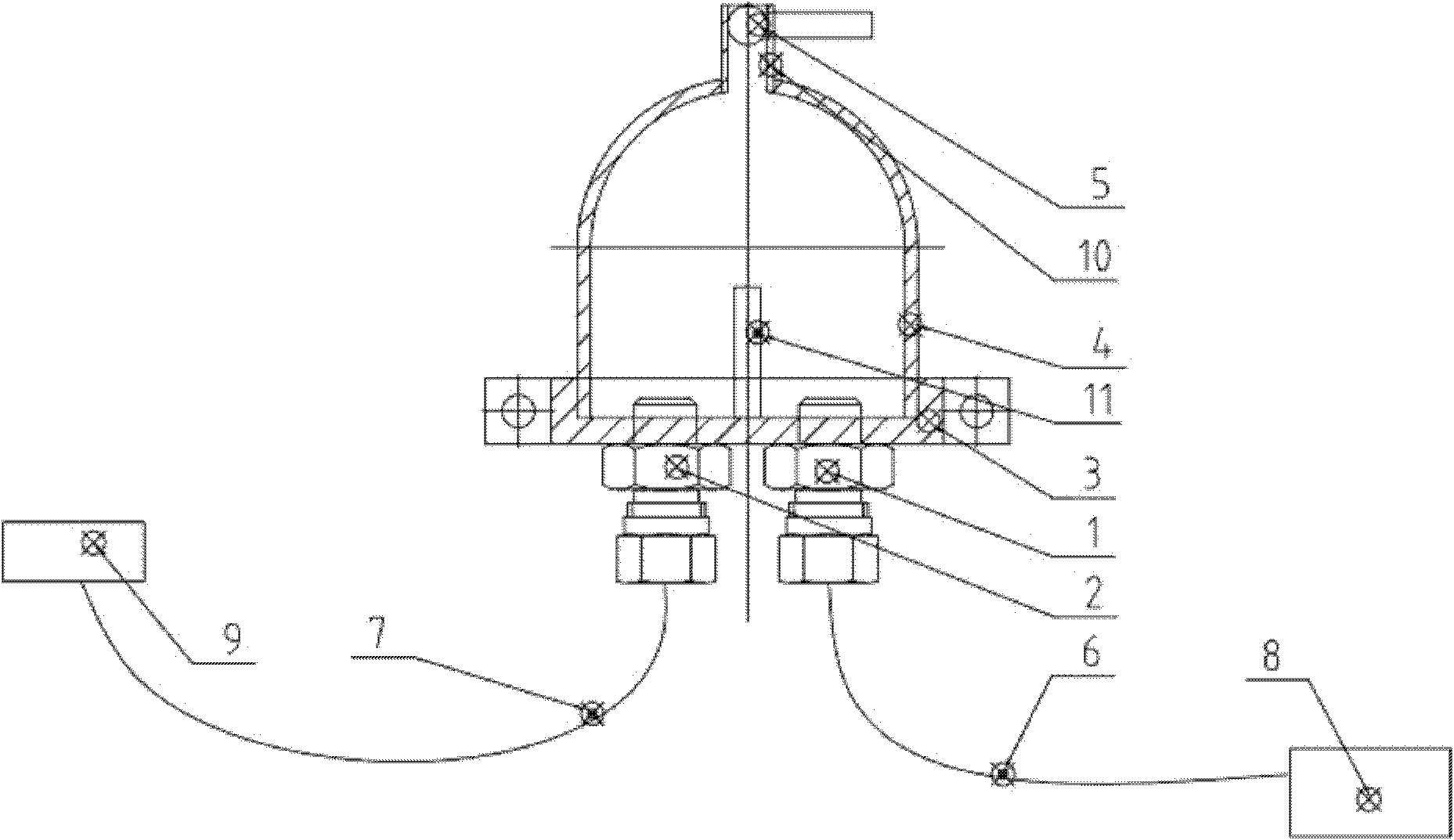
[0016] Such as figure 1 As shown, an exhaust system for passenger car clutches, including exhaust valve oil outlet joint 1, exhaust valve oil inlet joint 2, exhaust valve base 3, transparent cover 4, deflation ball valve 5, clutch oil outlet pipe 6. Clutch oil inlet pipe 7, clutch sub-pump 8, clutch master cylinder 9, air release ball valve base 10, the exhaust valve oil outlet joint 1 is connected with the clutch sub-pump 8 through the clutch oil outlet pipe 6, the exhaust valve The oil inlet joint 2 of the air valve is connected with the clutch master cylinder 9 through the oil inlet pipe 7 of the clutch. The base 3 of the exhaust valve is connected with the transparent cover 4 to form an accommodating space. The gas valve oil inlet joint 2 respectively passes through the exhaust valve base 3 and communicates with the accommodation space. The deflated ball valve base 3 is fixed on the upper end of the transparent cover 4, and the described deflated ball valve 5 is located on...


PUM


Abstract

The invention relates to an exhaust system for a passenger car clutch, which comprises an exhaust valve fuel outlet joint, an exhaust valve fuel inlet joint, an exhaust valve base, a transparent cover, a vent ball valve, a clutch fuel outlet pipe, a clutch fuel inlet pipe, a clutch branch cylinder, a clutch master cylinder and a vent ball valve base; the exhaust valve fuel outlet joint is connected with the clutch branch cylinder through the clutch fuel outlet pipe; the exhaust valve fuel inlet joint is connected with the clutch master cylinder through the clutch fuel inlet pipe; the exhaust valve base is connected with the transparent cover to form a containing space; the exhaust valve fuel outlet joint and the exhaust valve fuel inlet joint respectively penetrate through the exhaust valve base and are communicated with the containing space; the vent ball valve base is fixed on the upper end of the transparent cover; and the vent ball valve is arranged on the vent ball valve base. Compared with the prior art, the invention has the advantages of wide application range, high safety and reliability, favorable sealing property and the like, and is convenient to overhaul.

Description

technical field [0001] The invention relates to a clutch-related technology, in particular to an exhaust system for a passenger car clutch. Background technique [0002] At present, the clutch slave cylinder and the clutch master cylinder are connected by copper pipes, and the working medium is anti-wear ashless hydraulic oil. Due to the complex working conditions of the vehicle, the quality of the oil varies. Bubbles will be generated in the clutch oil pipe, and the clutch will not work smoothly after the bubbles are generated, and the workload of removing the bubbles is large, and the maintainability is not good. In the original system, the clutch oil pipe needs to be disassembled when exhausting. After the oil pipe is disassembled many times, it will wear and tear, causing the clutch oil pipe to leak oil at the joint. Contents of the invention [0003] The object of the present invention is to provide an exhaust system for passenger car clutches with wide application ...

Claims


Application Information

Patent Timeline
Patent Type & Authority Applications(China)
IPC IPC(8): F15B21/04
Inventor 段术林黄晓斌高岚
Owner ZHANGZHOU JINLONG BUS
Learn More