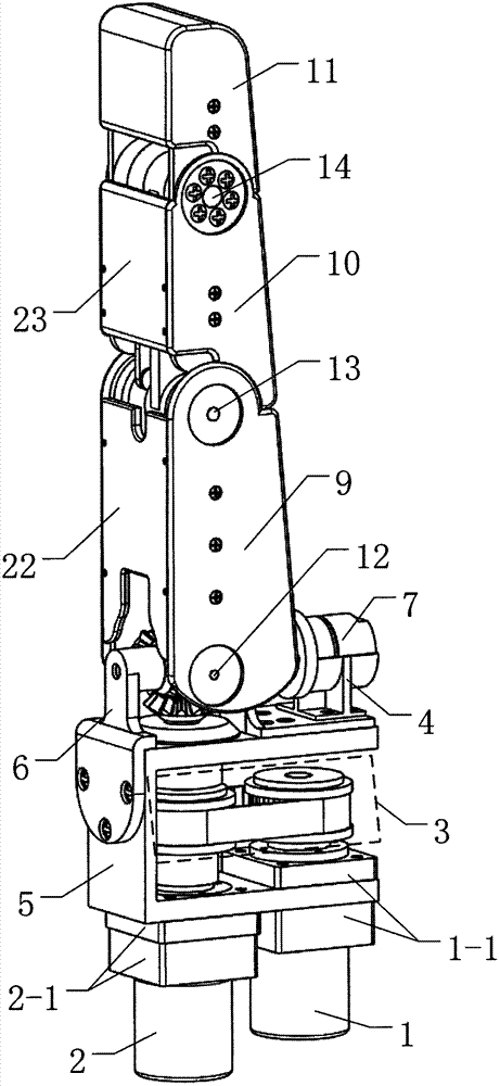
Finger structure of skillful hand of fruit picking robot
A picking robot and dexterous hand technology, applied in picking machines, manipulators, program-controlled manipulators, etc., can solve the problems of poor flexibility, single function, low adaptability of fruit shape, etc., to achieve convenient maintenance, stable transmission, reduced complexity and The effect of maintenance costs
- Summary
- Abstract
- Description
- Claims
- Application Information
AI Technical Summary
Problems solved by technology
Method used
Image
Examples
specific Embodiment approach 1
[0023] Specific implementation mode one: asfigure 1 , figure 2 , Figure 4 , Figure 5 and Figure 7 Shown, the fruit picking robot dexterous hand finger structure described in the present embodiment is by motor I (1), motor II (2), motor III (7), pedestal (5), the first phalanx (19), middle Knuckles (20), terminal knuckles (21), belt transmission mechanism I (3), front support (6), rear support (8), gear differential mechanism (15), belt transmission mechanism II (16), coupling Link transmission mechanism (17), cross shaft (12), proximal knuckle joint shaft (13), end knuckle joint shaft (14), first knuckle shell (9), middle knuckle shell (10), The end knuckle shell (11), the first knuckle pad cover (22) and the middle knuckle pad cover (23); motor I (1) and motor II (2) are fixed side by side on the base frame ( 5) and fixed by the fastening kit I (1-1) and fastening kit II (2-1) respectively, the motor III (7) is fixed on the rear support ( 8), the front support (6) an...
specific Embodiment approach 2
[0024] Specific implementation mode two: as figure 2 , image 3 , Figure 4 and Figure 7 As shown, the second driving synchronous pulley (31) of the belt drive mechanism II (16) described in this embodiment is limited by the retaining ring (24) and the first knuckle right side plate (35) to move axially, The second driven synchronous pulley (43) of the belt transmission mechanism II (16) is fixedly connected with the proximal knuckle shaft (13), and the lower end of the connecting bracket (42) of the middle knuckle (20) is connected with the proximal knuckle. The knuckle joint shaft (13) is fixedly connected and its axial movement is limited by the stop washer, and the connecting bracket (42) of the middle phalanx (20) is connected with the left side plate (38) of the middle phalanx and the right side plate (37) of the middle phalanx. ) is fixedly connected, the upper side end of the connecting bracket (42) of the middle phalanx (20) is fixedly connected with the terminal...
specific Embodiment approach 3
[0025] Specific implementation mode three: as Figure 5 , Figure 6 As shown, the gear differential mechanism (15) described in this embodiment consists of the first driving bevel gear (25), the first intermediate bevel gear (26), the first driven bevel gear (27), the second driving bevel gear (28), the second intermediate bevel gear (29), the second driven bevel gear (30) and the cross shaft (12), the first driving bevel gear (25), the first intermediate bevel gear (26) The module is the same as the first driven bevel gear (27), and the axis lines are vertical in pairs, wherein the first driving bevel gear (25) and the first driven bevel gear (27) are identical, and the first intermediate bevel gear ( 26) Engage with the first driving bevel gear (25) and the first driven bevel gear (27) at the same time, and the first intermediate bevel gear (26) and the first driven bevel gear (27) are respectively rotated and socketed on the cross shaft ( 12) the rear side and the left si...
PUM
 Abstract
Description
Claims
Application Information
 - R&D
- Intellectual Property
- Life Sciences
- Materials
- Tech Scout
- Unparalleled Data Quality
- Higher Quality Content
- 60% Fewer Hallucinations
Browse by: Latest US Patents, China's latest patents, Technical Efficacy Thesaurus, Application Domain, Technology Topic, Popular Technical Reports.
© 2025 PatSnap. All rights reserved.Legal|Privacy policy|Modern Slavery Act Transparency Statement|Sitemap|About US| Contact US: help@patsnap.com


