Control method for vacuum pollution of moving part and cable in optical system

A technology for moving parts and optical systems, applied in chemical instruments and methods, cleaning methods and utensils, and dust removal, etc., can solve the problems of organic pollutant release, long molecular free path, saturated vapor pressure, etc., to reduce the overall cost, Guaranteed to work properly

Active Publication Date: 2014-08-13
SOUTHEAST UNIV
View PDF15 Cites 0 Cited by
  • Summary
  • Abstract
  • Description
  • Claims
  • Application Information

AI Technical Summary

Problems solved by technology

However, in these systems, due to the adjustment of the position of moving loads such as optical elements, detection devices, and driving devices, it is often necessary to use moving parts such as motors, gears, and screw rods, and these parts need certain lubricating materials during work. Materials such as enameled wires and external wires are used. Because these materials contain plasticizers, volatile organic compounds and other components, the saturated vapor pressure is high, and organic pollutants will inevitably be released.
Therefore, in order to reduce the influence of pollution of these materials in the system, materials with low saturated vapor pressure such as fluorine oil are often used as lubricants, low-gassing driving components such as vacuum motors are used as power, and silicone rubber and polytetrafluoroethylene are used. Sheathed wires, etc., although these methods release a small amount of pollutants, they are systems that require high cleanliness. Since these components are directly exposed to the optical system, especially when the system is a vacuum system, the molecular free path is relatively long. These volatiles still have a relatively large impact on the system

Method used


Image

  • Control method for vacuum pollution of moving part and cable in optical system
  • Control method for vacuum pollution of moving part and cable in optical system
  • Control method for vacuum pollution of moving part and cable in optical system

Examples


Embodiment Construction

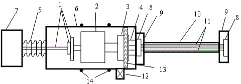
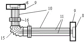
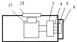
[0027] The device of the present invention is composed of the moving part 1 of the transmission mechanism, the motor 2, the control circuit board 3, the cable 4, the first bellows 5, the transmission mechanism cavity 6, the controlled motion carrier 7, the cable joint 8, the sealing cover 9, the wire Cable outer casing 10, cable 11, vacuum valve 12 and other components.

[0028] Parts and materials that contain lubricants, plasticizers, organic polymer materials, such as motors, transmission mechanisms, control circuit boards, cables, cameras, and light sources, that generate volatile organic pollutants and particle pollutants under vacuum and laser light conditions , by adopting a vacuum sealing method, these components and materials are sealed in the cavity of the transmission mechanism, and the movement of the bellows connected to the cavity is controlled by the transmission mechanism, thereby driving the controlled motion carrier 7 .

[0029] The connection between moving ...


PUM


Abstract

The invention relates to a control method for vacuum pollution of a moving part and a cable in an optical system. According to a vacuum sealing method, a moving part (1), a motor (2), a control circuit board (3) and a cable (4) of a transmission mechanism are sealed in a space formed by connecting a corrugated pipe (5) and a transmission mechanism cavity (6); the motor (2) is connected with one end of the moving part (1) of the transmission mechanism; the other end of the moving part (1) of the transmission mechanism is connected with a moveable end of the corrugated pipe (5), so as to control the stretching and moving of the corrugated pipe (5); the exterior of the corrugated pipe (5) is connected with a to-be-controlled moving carrier (7), so as to drive the moving carrier (7) to move; a cable connector (8) behind the control circuit board (3) is sealed by using a sealing cover (9); an external cable casing pipe (10) is connected with the outer side of the sealing cover (9); and a cable (11) passes through the interior of the external cable casing pipe (10). By adopting a vacuum sealing shielding method, the pollution to the optical system caused by a pollution source which is irradiated by strong light is avoided.

Description

technical field [0001] The invention relates to the control technology of pollutants in the high-power laser optical system, especially the organic pollutants released in vacuum from materials such as motors, transmission mechanisms, etc. A control method for optical system pollution caused by the deposition of generated particles and debris on optical components. This technology can be applied to the control of pollutants in moving parts in high-power laser light source, extreme ultraviolet light source, ultra-clean analytical instrument, ultra-high vacuum and other systems, which can improve the cleanliness of the system and the working life of optical components. Background technique [0002] In high-power laser pump light sources and applied optical systems, extreme ultraviolet light source optical systems, and ultra-clean analytical instruments, the deposition of volatile organic pollutants on the optical surface will directly affect the performance and life of optical ...

Claims


Application Information

Patent Timeline
Patent Type & Authority Patents(China)
IPC IPC(8): B08B15/02
Inventor 张晓兵肖梅康学军夏柱红祁争健
Owner SOUTHEAST UNIV
Why Eureka
Try Eureka