Light emitting diode (LED) drive circuit and LED lighting device
A LED drive and circuit technology, applied in lighting devices, electric lamp circuit layout, electric light source, etc., can solve the problems of high cost and complex circuit structure, and achieve the effect of solving high cost, complex circuit structure and reducing circuit cost
- Summary
- Abstract
- Description
- Claims
- Application Information
AI Technical Summary
Problems solved by technology
Method used
Image
Examples
Embodiment 1
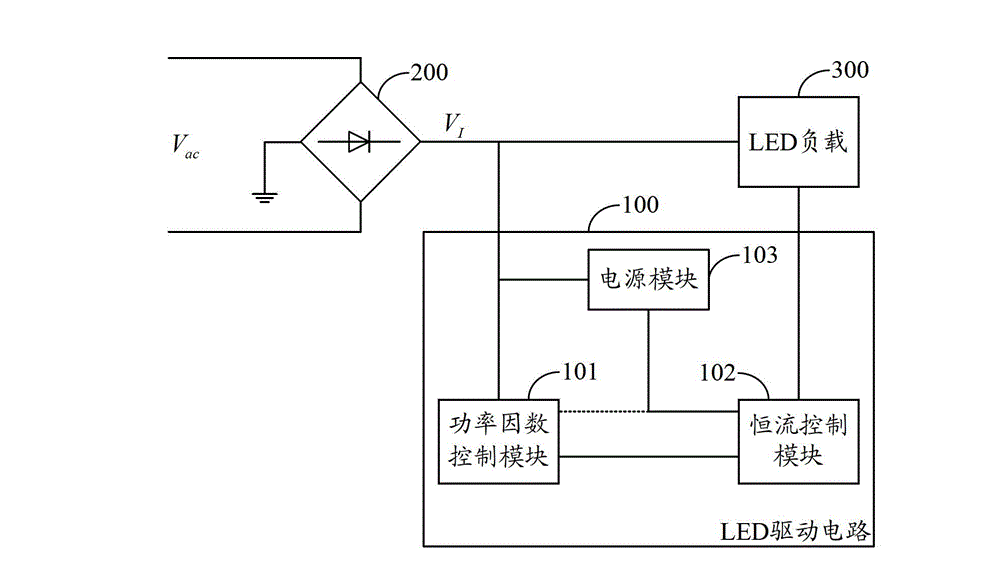
[0017] figure 1 The module structure of the LED driving circuit provided by the first embodiment of the present invention is shown. For the convenience of description, only the parts related to the present invention are shown, and the details are as follows:
[0018] The LED drive circuit 100 is connected with the rectifier bridge circuit 200 and the LED load 300, and the rectifier bridge circuit 200 converts the mains AC signal V ac Converted into a sine half-wave electrical signal V I , the input end of the LED load 300 is connected to the output end of the rectifier bridge circuit 200, and the LED drive circuit 100 includes:
[0019] The power factor control module 101 is connected with the output terminal of the rectifier bridge circuit 200, and is used for the sine half-wave electric signal V outputted by the rectifier bridge circuit 200 I are sampled and correspondingly generate a half-sine wave electrical signal with V I The first in-phase electrical signal in the sa...
Embodiment 2
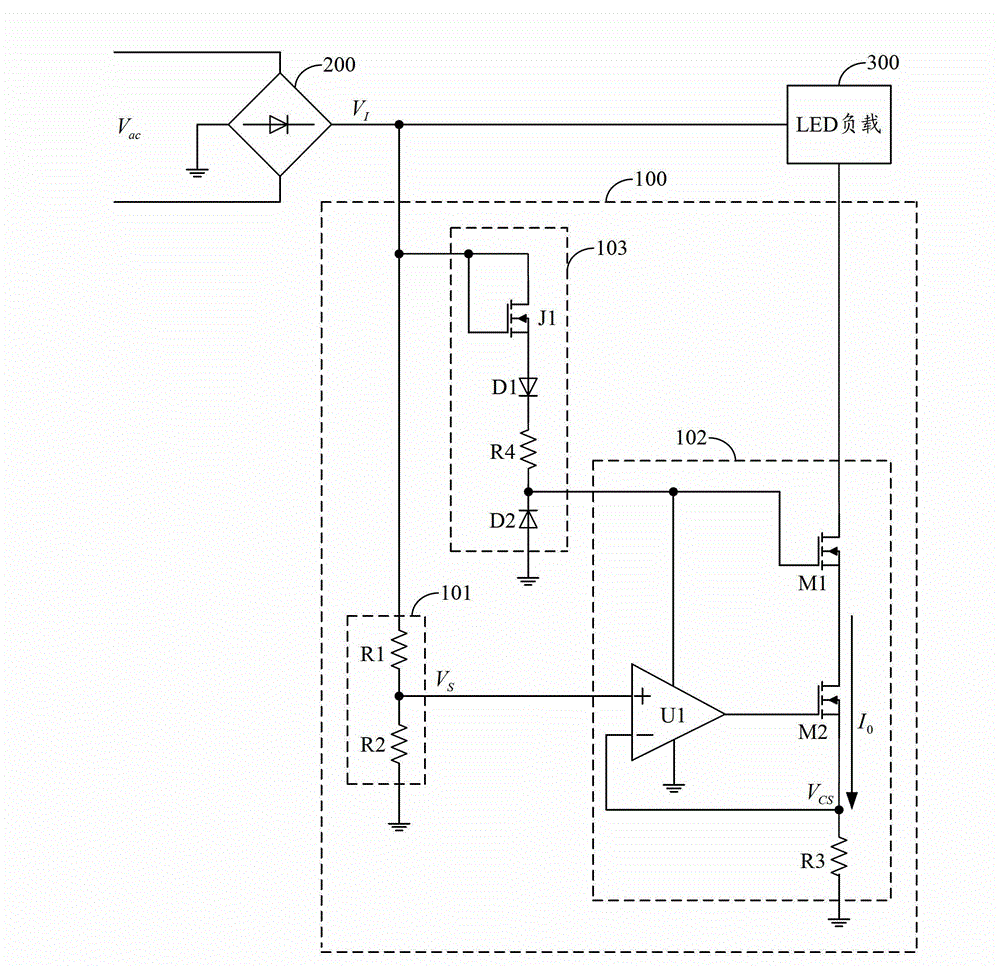
[0024] figure 2 An example circuit structure of the LED driving circuit provided by the second embodiment of the present invention is shown. For the convenience of description, only the parts related to the present invention are shown, and the details are as follows:
[0025] In this embodiment, the LEDs inside the LED load 300 may be connected in series, in parallel or in combination.
[0026] As an embodiment of the present invention, the power module 103 includes:
[0027] N-channel J-type field effect transistor J1, diode D1, resistor R4 and diode D2;
[0028] The gate and drain of the N-channel J-type field effect transistor J1 are connected to the output terminal of the rectifier bridge circuit 200, and the anode and cathode of the diode D1 are respectively connected to the source of the N-channel J-type field effect transistor J1 and the resistor R4. The first end is connected, the second end of the resistor R4 is connected to the cathode of the diode D2, and the ano...
Embodiment 3
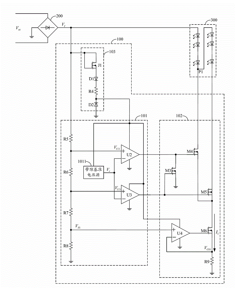
[0053] image 3 An example circuit structure of the LED driving circuit provided by the third embodiment of the present invention is shown. For the convenience of description, only the parts related to the present invention are shown, and the details are as follows:
[0054] In this embodiment, the LEDs in the LED load 300 are connected in series, wherein the output terminal of the LED lamp group 301 is the internal circuit node P1 of the LED load 300; the circuit structure of the power module 103 is the same as that provided by the second embodiment of the present invention consistent, so no further details are given.
[0055] As an embodiment of the present invention, the power factor control module 101 includes:
[0056] Resistor R5, resistor R6, comparator U2, resistor R7, comparator U3, resistor R8, resistor R9 and bandgap reference voltage source 1011;
[0057] The first terminal of the resistor R5 is connected to the output terminal of the rectifier bridge circuit 200...
PUM
 Abstract
Description
Claims
Application Information
 - R&D
- Intellectual Property
- Life Sciences
- Materials
- Tech Scout
- Unparalleled Data Quality
- Higher Quality Content
- 60% Fewer Hallucinations
Browse by: Latest US Patents, China's latest patents, Technical Efficacy Thesaurus, Application Domain, Technology Topic, Popular Technical Reports.
© 2025 PatSnap. All rights reserved.Legal|Privacy policy|Modern Slavery Act Transparency Statement|Sitemap|About US| Contact US: help@patsnap.com


