Leakage monitoring chip for leakage protector

A leakage protector and monitoring chip technology, which is applied to emergency protection circuit devices, emergency protection devices with automatic disconnection, electrical components, etc., can solve problems such as difficult control of leakage action current, difficult production, and malfunction of protectors. , to avoid the leakage action current exceeding the standard and serious malfunction, the production and debugging are simple and easy, and the effect of protecting personal safety

Active Publication Date: 2014-12-03
田子欣
View PDF4 Cites 3 Cited by
  • Summary
  • Abstract
  • Description
  • Claims
  • Application Information

AI Technical Summary

Problems solved by technology

It can only monitor the leakage fault of the main circuit and the zero live wire (that is, the two poles are on and off), and cannot monitor the live fault of the ground wire at the same time.
In order to achieve the function of three-pole on-off, some use a monitoring circuit directly driven by a thyristor (without signal amplification), some use a parallel input method to add a monitoring circuit on an ordinary single-input chip circuit, and some directly Add an ordinary single-input chip (that is, two ICs) to drive the monitoring circuit; these measures have many disadvantages, such as when the main circuit and the ground wire have a leakage fault at the same time, the actual value of the leakage action current (that is, the main circuit and the ground wire) will appear. The sum of the leakage action current of the ground wire) far exceeds the national standard, which seriously threatens personal safety; some main circuits will have double and subtractive phenomena at the same time, that is, the leakage action current of the L or N line will exceed the safety standard, and the other In phase N or L line, the leakage action current is too small, which leads to serious malfunction of the protector; moreover, the leakage action current is not easy to control, the circuit structure is complex, there are many components, the creepage distance is insufficient, the failure rate is high, and the production is difficult. Wait

Method used


Image

  • Leakage monitoring chip for leakage protector
  • Leakage monitoring chip for leakage protector
  • Leakage monitoring chip for leakage protector

Examples


Embodiment Construction

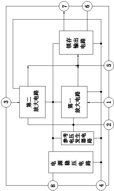
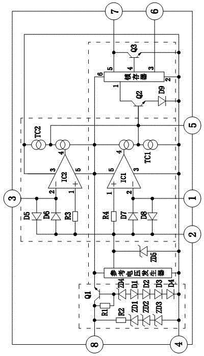
[0012] The present invention will be described in further detail below in conjunction with accompanying drawing and embodiment:

[0013] like figure 1 As shown, it is a leakage monitoring chip of a leakage protector, including a power supply voltage stabilization circuit, a reference voltage generator circuit and a latch output circuit, wherein the power supply voltage stabilization circuit is a reference voltage generator circuit, a latch output circuit And the following circuit provides working voltage, the input end of the power supply voltage stabilizing circuit is the 8, 4 pins of the electric leakage monitoring chip; It also includes the first amplifying circuit and the second amplifying circuit with the same circuit structure and performance, one of the first amplifying circuit The input end is electrically connected with one input end of the second amplifying circuit and used as a common input end to connect to an external circuit. This end is pin 2 of the leakage mon...


PUM


Abstract

The invention relates to a leakage monitoring chip for a leakage protector. The leakage monitoring chip comprises a power voltage regulator circuit, a reference voltage generator and a latching output circuit, wherein the power voltage regulator circuit is used for providing working voltage for the reference voltage generator and the latching output circuit; the leakage monitoring chip further comprises a circuit structure and a first amplifying circuit and a second amplifying circuit which have the same performance; an input end of a first differential amplifier circuit is electrically connected with an input end of a second differential amplifier circuit, and the end is used as the public input end to connect with an external circuit; the other input end of the first differential amplifier circuit is connected with the external circuit; the other input end of the second differential amplifier circuit is connected with the external circuit; the output end of the first amplifying circuit and the output end of the second amplifying circuit are electrically connected with the input end of the latching output circuit respectively; the reference voltage generator circuit is used for respectively providing reference voltage for the input ends of the first differential amplifier circuit and the second differential amplifier circuit. The leakage monitoring chip provided by the invention has the advantages that the leakage faults of the main loop and the ground wire can be monitored synchronously; and the two fault action current can be adjusted randomly in the scope of national safety standards; the leakage monitoring chip works stably and reliably and the personal safety can be more effectively protected.

Description

technical field [0001] The invention relates to a leakage monitoring chip of a leakage protector. Background technique [0002] The current leakage monitoring chips of existing leakage protectors all have only one amplification and input circuit, such as 54123 and 4145. It can only monitor the leakage fault of the main circuit and the zero live wire (that is, the two poles are on and off), and cannot monitor the live fault of the ground wire at the same time. In order to achieve the function of three-pole on-off, some use a monitoring circuit directly driven by a thyristor (without signal amplification), some use a parallel input method to add a monitoring circuit on an ordinary single-input chip circuit, and some directly Add an ordinary single-input chip (that is, two ICs) to drive the monitoring circuit; these measures have many disadvantages, such as when the main circuit and the ground wire have a leakage fault at the same time, the actual value of the leakage action c...

Claims


Application Information

Patent Timeline
Patent Type & Authority Patents(China)
IPC IPC(8): H02H3/33
Inventor 田子欣田玉江
Owner 田子欣
Why Eureka
Try Eureka