
Sealing detection fixture

A seal detection and fixture technology, applied in the detection field, can solve problems affecting production efficiency, simulation is not realistic enough, processing accuracy is not high, etc., to achieve the effect of improving processing accuracy and service life, ensuring consistency and stability

Inactive Publication Date: 2012-10-10
赛龙通信技术(深圳)有限公司
View PDF0 Cites 17 Cited by
  • Summary
  • Abstract
  • Description
  • Claims
  • Application Information

AI Technical Summary

Problems solved by technology

[0002] 1. The existing sealing detection technology only checks the possible leaking locations of product parts and components. If there are multiple leaks in the parts, it is necessary to carry out multi-station testing, which will affect production efficiency.
[0003] 2. The existing sealing detection technology uses air blowing from the inside to simulate the pressure of the product in deep water. This kind of air blowing from the inside produces positive pressure, which is contrary to the actual product pressure, and the simulation is not realistic enough.
[0004] 3. The existing sealing detection technology uses the method of bubbling to observe whether the product has leakage, and judges whether the component has leakage according to the number of bubbling. This kind of judgment method is highly subjective, non-quantifiable, and easy to misjudge
[0005] 4. The existing sealing detection technology has the characteristics of low processing accuracy and short service life in the manufacture of jigs

Method used


Image

  • Sealing detection fixture
  • Sealing detection fixture
  • Sealing detection fixture

Examples


Embodiment Construction

[0020] In order to enable those skilled in the art to better understand the technical solutions of the present invention, the present invention will be further described in detail below in conjunction with the accompanying drawings and embodiments.

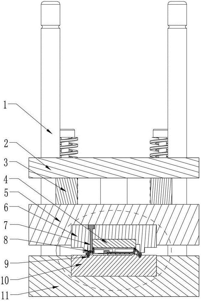
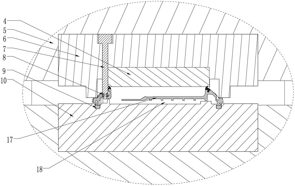
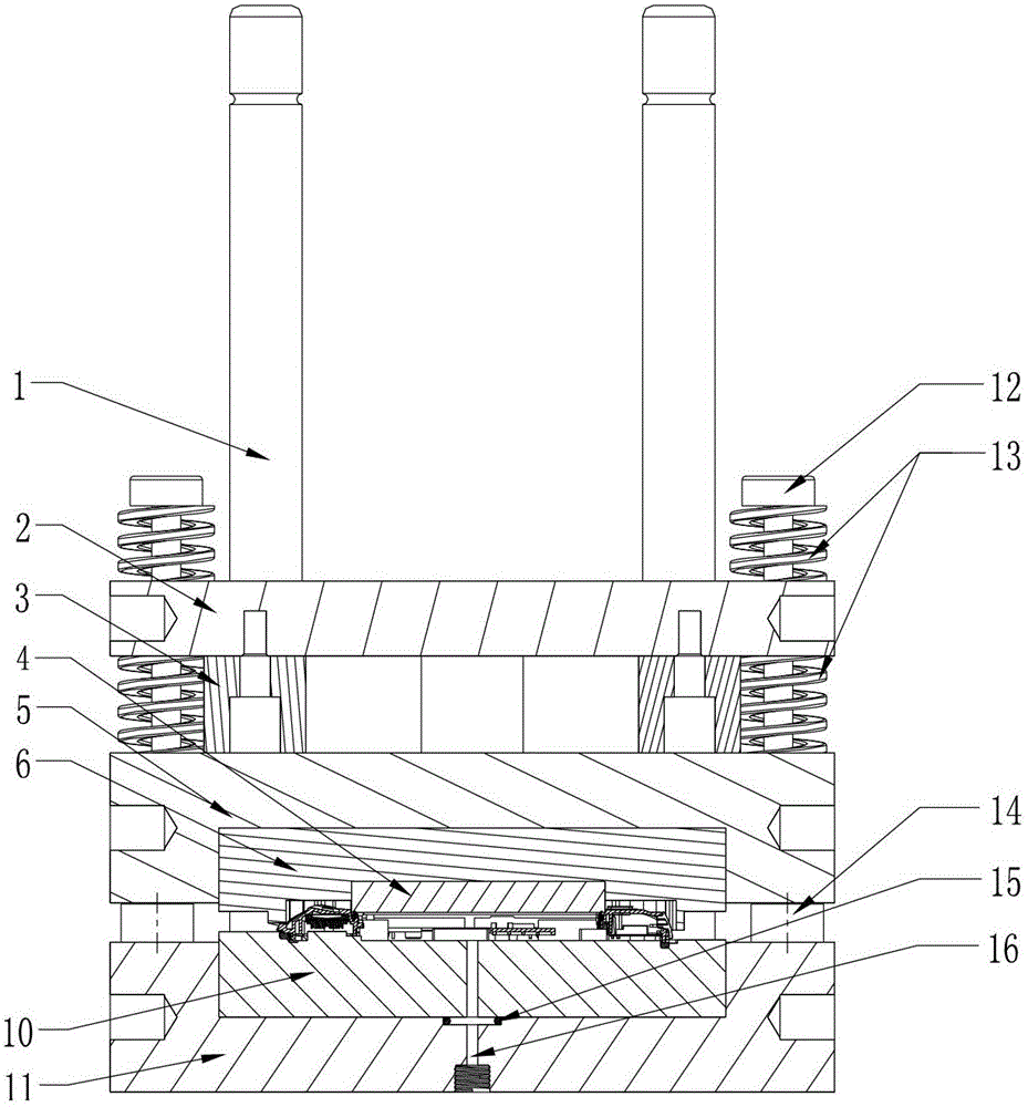
[0021] The sealing detection jig of the present invention is a device for testing the waterproofness of semi-finished components. The product to be tested is composed of multiple small plastic parts assembled and combined, and has multiple matching stations. There are leakage problems after assembly of semi-finished components caused by poor assembly of multiple coordinating stations and defects of small plastic parts. Semi-finished products need to be tested.

[0022] Such as figure 1 , figure 2 and image 3 As shown, the seal detection fixture can be divided into two parts, the lower mold and the upper mold. The upper surface of the lower mold is provided with an annular seal 9 that contacts the parting surface of the produ...


PUM


Abstract

The invention provides a sealing detection fixture. The sealing detection fixture comprises a lower die and an upper die, wherein an annular sealing member which is contacted with a parting surface of a product to be tested is arranged on the upper surface of the lower die; and an exhaust hole is formed in the lower die in a ring of the annular sealing member. The upper die is mounted and connected with an air cylinder; when the upper die presses towards the lower die, a closed cavity from which air can be extracted is formed between the product to be tested and the sealing detection fixture; a sealing ring for sealing a screw hole of the product to be tested is arranged on the upper die; and a mold core insert for sealing a battery compartment of the product to be tested is arranged on the upper die. The sealing detection fixture can be used for integrally checking product parts and assemblies and testing at a time to judge whether the parts meet the requirement or not. The negative pressure generated by exhausting from the inside is matched with the stress on an actual product in deep water, and thus the simulation is more vivid. The internal air pressure is displayed in real time by using a barometer; the quantitative judgment is realized by the change of an air pressure value and is fed back to the computer, and thus automatic judgment is finished.

Description

technical field [0001] The invention relates to the technical field of detection, in particular to the structure of a jig used in the sealing detection technology. Background technique [0002] 1. The existing sealing detection technology only checks the possible leaking locations of product parts and components. If there are multiple leaks in the parts, it is necessary to carry out multi-station testing, which will affect the production efficiency. [0003] 2. The existing sealing detection technology uses air blowing from the inside to simulate the pressure of the product in deep water. This kind of air blowing from the inside produces positive pressure, which is contrary to the actual product pressure, and the simulation is not realistic enough. [0004] 3. The existing sealing detection technology uses the method of bubbling to observe whether the product leaks, and judges whether the component leaks according to the number of bubbling. This kind of judgment method is hi...

Claims


Application Information

Patent Timeline
IPC IPC(8): G01M3/26
Inventor 曾广旨吴健安李立恒朱永球
Owner 赛龙通信技术(深圳)有限公司
Learn More