Anti-floating retention structure

A retention, stainless steel sleeve technology, applied in structural elements, building components, building structures, etc., can solve problems such as substandard thickness of steel protective layer, poor control of steel protective layer, and inapplicability

Inactive Publication Date: 2012-10-10
佛山班仕达节能新材料科技有限公司
View PDF6 Cites 3 Cited by
  • Summary
  • Abstract
  • Description
  • Claims
  • Application Information

AI Technical Summary

Problems solved by technology

The traditional pads are granite waste pads, cement mortar pads or professional plastic pads, etc. The following problems exist in the use of the above-mentioned pads: 1. Granite waste pads are not easy to bind, and During the concrete pouring process, the vibrator can easily cause the pads to fall off, making it difficult to control the protective layer of steel bars; 2. The production of cement mortar pads is time-consuming and labor-intensive, and the pads are not strong enough, which can easily cause the pads to be crushed , so that the control of the steel protection layer is not good; 3. Although professional plastic pad products are more convenient for construction, their use cost is relatively large and the scope of use is small. Walls and other parts are not applicable; 4. The traditional pads are only placed on the formwork. When pouring, the steel bars and the inner mold will drive the steel bars to float up under the buoyancy of the cement mixture, resulting in the thickness of the protective layer of the steel bars. Engineering quality; 5. And these pads cannot be used in conjunction with the inner mold. When the inner mold needs to be installed, an additional fixed anti-floating structure is required, which wastes manpower and material resources and affects construction efficiency.

Method used


Image

  • Anti-floating retention structure
  • Anti-floating retention structure
  • Anti-floating retention structure

Examples


Embodiment Construction

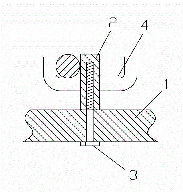
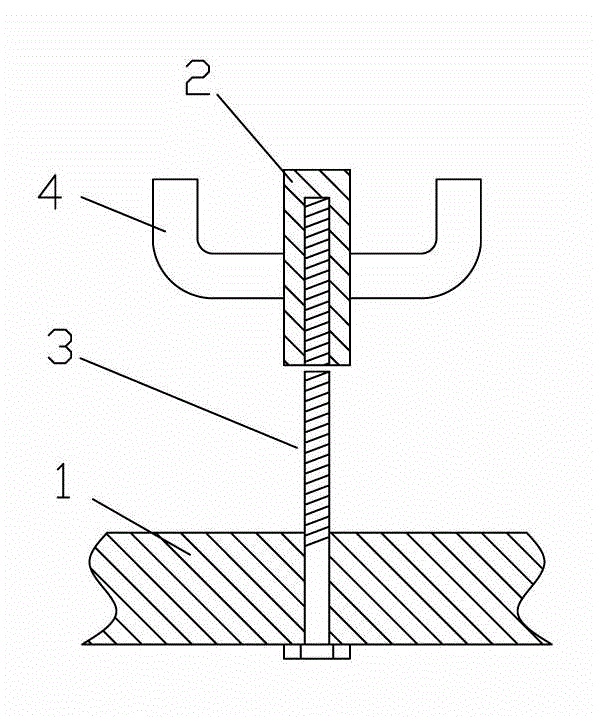
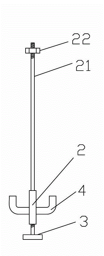
[0018] refer to Figure 1 to Figure 5 , an anti-floating retention structure provided by the present invention includes a template 1 and a stainless steel sleeve 2, the bottom of the stainless steel sleeve 2 is provided with an internally threaded hole, a "T" bolt 3 is inserted into the internally threaded hole from the bottom of the template 1 and The stainless steel sleeve 2 is fixed on the template 1, and the side of the stainless steel sleeve 2 is extended outward with one or more brackets 4 for supporting steel bars. In this embodiment, the end of the "T" bolt 3 is in the shape of a "7", where the end of the "T" bolt 3 can also be in the shape of a "cross" or other shapes, with the same technology Effect. In order to ensure that the stainless steel sleeve 2 is not corroded, the stainless steel sleeve 2 is made of stainless steel such as 304 that will not rust. After the construction is completed, all the stainless steel sleeves 2 are directly buried in the cement floor, ...


PUM


Abstract

The invention discloses an anti-floating retention structure which comprises a form and a stainless steel sleeve. The bottom of the stainless steel sleeve is provided with an internal threaded hole. A 'T'-shaped bolt is inserted into the internal threaded hole from the bottom of the form to fix the stainless steel sleeve to the top of the form. One or a plurality of brackets for holding rebars extend out from the lateral sides of the stainless steel sleeve. As the brackets for holding rebars extend out from the lateral sides of the stainless steel sleeve, the rebars on the form are fixed on the brackets after the 'T'-shaped bolt and the stainless steel sleeve are fixed on the form, and floating resisting is achieved for the rebars. Therefore, thickness of a rebar protective layer is guaranteed, and all rebars are protected by cement.

Description

technical field [0001] The invention relates to a building structure, in particular to an anti-floating and retaining structure, which is generally used to support and clamp steel bars or inner molds in beams or templates to ensure the thickness of the protective layer of steel bars or the position of the inner mold. Background technique [0002] In building construction, the reinforcement of reinforced concrete needs to be provided with a certain protective layer thickness from the concrete surface. In order to ensure this size, a spacer needs to be placed between the reinforcement and the formwork during construction. The traditional pads are granite waste pads, cement mortar pads or professional plastic pads, etc. The following problems exist in the use of the above-mentioned pads: 1. Granite waste pads are not easy to bind, and During the concrete pouring process, the vibrator can easily cause the pads to fall off, making it difficult to control the protective layer of s...

Claims


Application Information

Patent Timeline
Patent Type & Authority Applications(China)
IPC IPC(8): E04C5/18
Inventor 万旋枝
Owner 佛山班仕达节能新材料科技有限公司
Why Eureka
Try Eureka