
Multifunctional charger

A charging machine, multi-functional technology, applied in the direction of current collectors, electric vehicles, electrical components, etc., can solve the problems of large impact on the power grid, stop charging for a certain period of time, and poor initial charging quality, etc., to extend the service life and ensure accuracy , Improve the effect of charging quality

Inactive Publication Date: 2012-10-03
贵州天昱金泰电力建设工程有限公司
View PDF5 Cites 5 Cited by
  • Summary
  • Abstract
  • Description
  • Claims
  • Application Information

AI Technical Summary

Problems solved by technology

Therefore, capacitive chargers that use capacitors instead of rectifier transformers or thyristor step-downs have appeared on the market, and their power-saving effect is remarkable. It has been fully utilized, because a large number of capacitors are installed in the equipment. In order to solve the above problems, there is another function that uses capacitors to compensate reactive power for the power grid, and realizes that the charger can both charge and perform reactive power compensation.
However, this technical solution has the following deficiencies: (1) when the compensation function is realized, the compensation button is pressed manually, and all capacitors are put into the power grid at the same time, which has a large impact on the power grid; (2) when the battery is initially charged, it must be artificially Control the charging time, the first stage is 36 hours, and the second stage is 36 hours. When the temperature of the battery is high, it is possible to stop charging for a certain period of time to cool down, especially if the time is long, and the charging staff is changing shifts, etc., it may cause timing failure. If it is not accurate enough, it will lead to poor initial charging quality, which will seriously affect the quality and life of the battery; (3) When performing daily charging, use a time relay to control
The disadvantage of this control method is that when the power of the battery to be charged is seriously low, the set time may not be able to fully charge the battery, and when the battery to be charged has a certain amount of power and only a small amount of power needs to be charged, When the battery is connected to the charger, it must be charged to the set time before the power is cut off, so the battery may cause overcharging and seriously affect the service life of the battery; (4) There is no alarm device. After the battery is reversed, it is only a protection The charger cannot be started, and will not send out sound and light alarms, resulting in failures that cannot be resolved in time

Method used


Image

  • Multifunctional charger
  • Multifunctional charger
  • Multifunctional charger

Examples


Embodiment Construction

[0035] The technical solution of the present invention is further described below in conjunction with the accompanying drawings, but the scope of protection is not limited to the description.

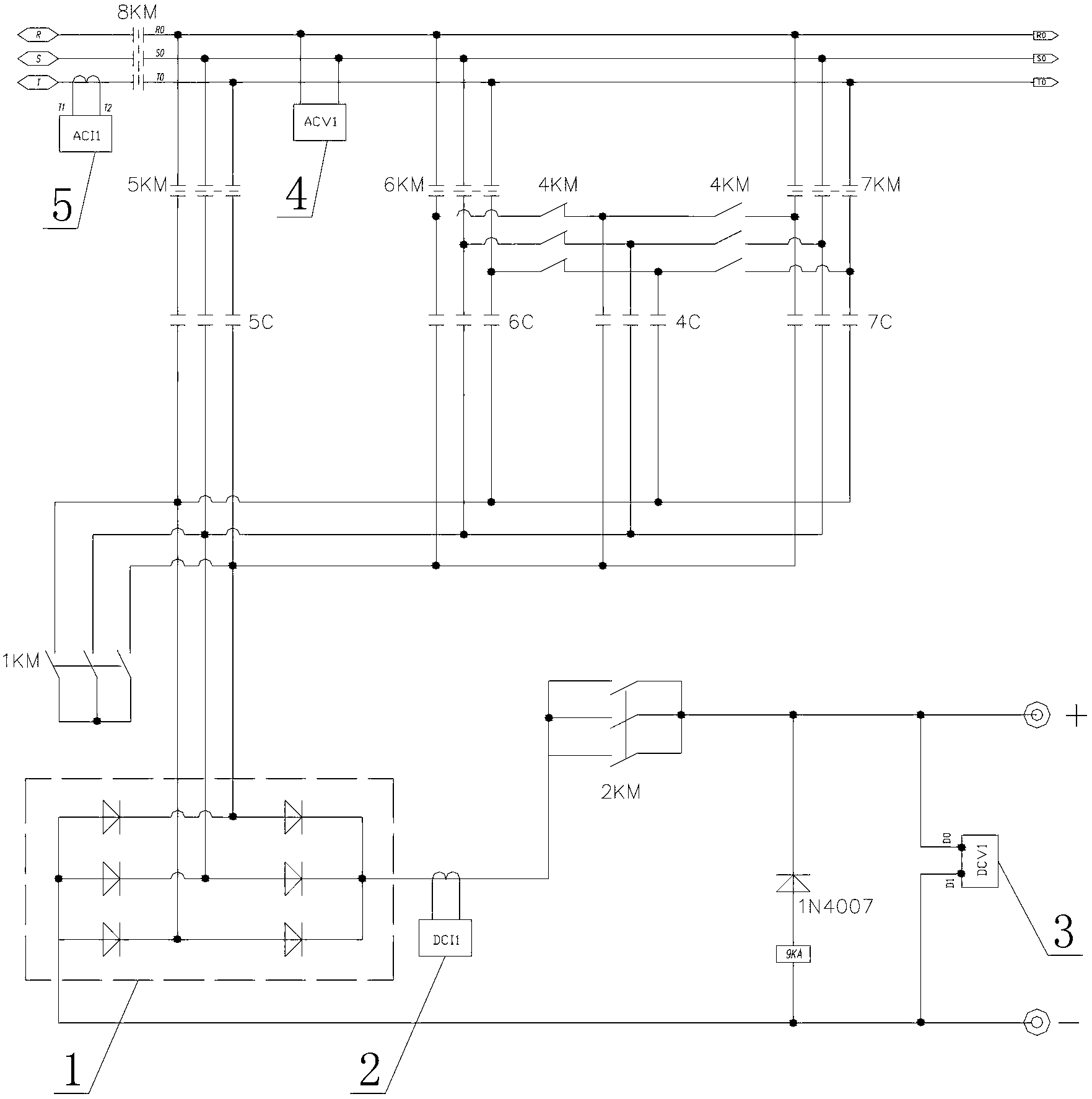
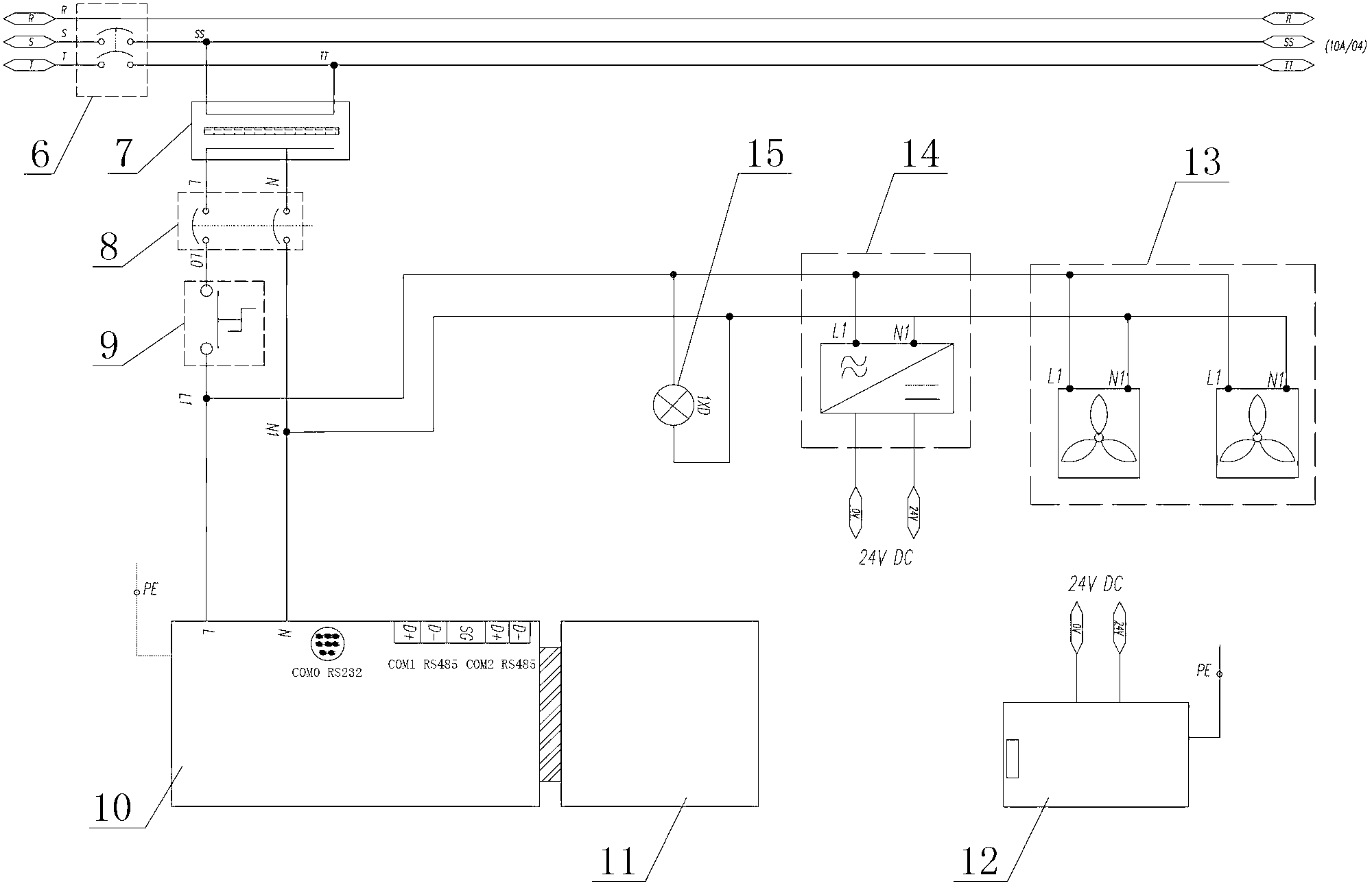
[0036] like Figure 1 to Figure 7 As shown, a multifunctional charger includes a charging circuit, a compensation circuit, a rectification circuit, an intelligent control system, a compensation contactor 1KM, a charging contactor 2KM, an AC contactor 8KM and a reverse relay 9KA. The rectification circuit consists of three The phase rectification full bridge 1 is composed of the AC arm of the three-phase rectification full bridge 1 respectively connected to the upper end of the compensation contactor 1KM and one end of the capacitor bank 4C, 5C, 6C, 7C, and the negative terminal of the DC output arm is connected to the negative pole of the DC output circuit of the charger After the positive pole of the DC output arm is connected in series with the 2KM main contact of the charging contact...


PUM


Abstract

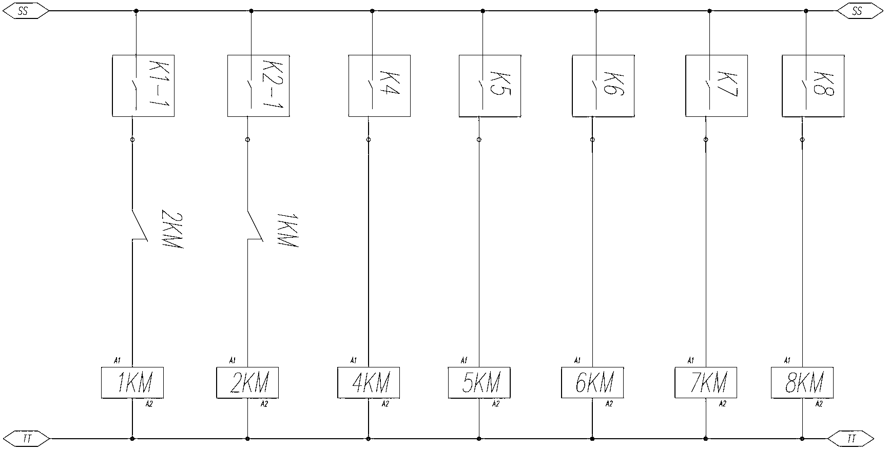
The invention discloses a multifunctional charger, which comprises a charging circuit, a compensating circuit, a rectifying loop, an intelligent control system, a compensating contactor 1KM, a charging contactor 2KM, an AC contactor 8KM and a reverse connection relay 9KA, wherein the compensating contactor 1KM and the charging contactor 2KM are subjected to electric interlocking by self auxiliary contact points on the control; when the charging contactor 2KM works, the charging circuit is formed, and when the compensating contactor 1KM works, the compensating circuit is formed; and an PLC (Programmable Logic Controller) module and a PLC host of the intelligent control system are in plugged connection, wherein the PLC host controls connection and disconnection of the compensating contactor 1KM and the charging contactor 2KM so as to realize the conversion between a charging state and a reactive power compensation state of the charger. The multifunctional charger realizes programmable automatic control by adopting an AC / DC current-voltage sensor and the PLC host, realizes the conversion between analog quantity and digital quantity by the PLC module, displays various working states and working parameters by using a touch display screen, realizes man-machine conversation and is high in automation degree.

Description

technical field [0001] The invention relates to a multifunctional charger, which belongs to the technical fields of power electronics technology and grid reactive power compensation. Background technique [0002] The charger is a general-purpose equipment that is inseparable from various industries such as aerospace, national defense communications, automobiles and ships, industrial and mining electromechanical, railway locomotives, port terminals, various types of electric vehicles, equipment maintenance, mining, storage and handling, cleaning equipment, electric power, etc. The scope is very wide. The charger commonly used in the market at present, its principle is to step down and rectify the AC power supply, and then charge various storage batteries, which belongs to the field of power electronics technology. [0003] Reactive power compensation is a reactive power compensation power supply. In order to meet the voltage level and economic operation requirements of the p...

Claims


Application Information

Patent Timeline
Patent Type & Authority Applications(China)
IPC IPC(8): H02J7/02
Inventor 曾天锐
Owner 贵州天昱金泰电力建设工程有限公司
Learn More