
Automatic capacity regulating distribution transformer and capacity regulating method thereof

A technology of distribution transformers and transformers, which is applied in the direction of transformers, variable transformers, inductors, etc., can solve the problems of small low-voltage opening distance of capacity-adjusting switches, reduce the current of low-voltage contacts, and reduce the degree of contact ablation, etc., to achieve extended Effects of service life, improved reliability, and reduced degree of ablation

Active Publication Date: 2012-10-03
北京博瑞莱智能科技集团有限公司
View PDF6 Cites 8 Cited by
  • Summary
  • Abstract
  • Description
  • Claims
  • Application Information

AI Technical Summary

Problems solved by technology

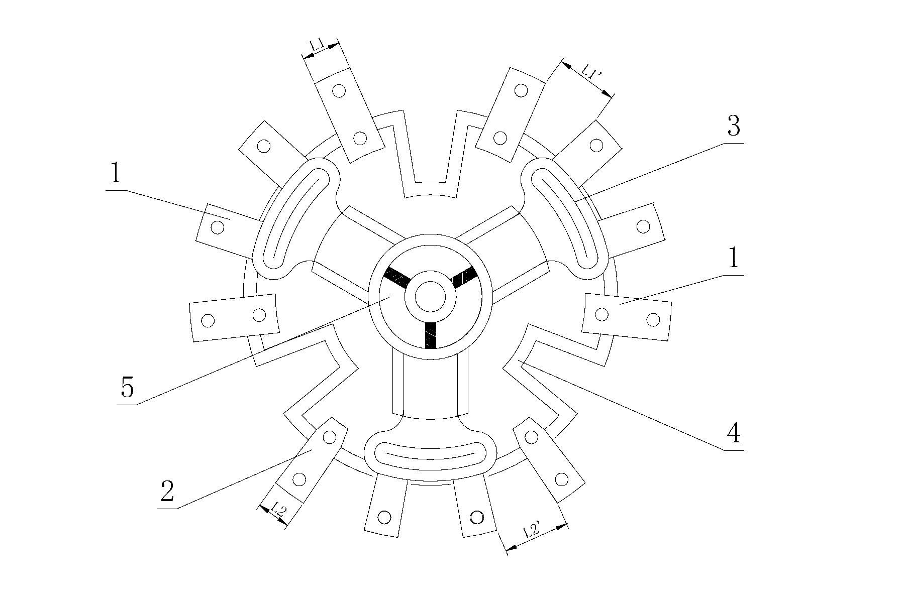
[0005] In view of the above problems, the present invention provides an automatic capacity adjustment distribution transformer and its capacity adjustment method, which can be automatically and quickly adjusted to a small capacity state for operation under light load, which solves the problem of large no-load loss of the power grid, and automatically and quickly adjusts to a low capacity state when the load is large. Large-capacity operation avoids the "small horse-drawn cart" that causes the transformer to burn out; the low-voltage opening distance of the capacity adjustment switch is smaller than the high-voltage opening distance, so that the low-voltage winding completes the conversion before the high-voltage winding, which greatly reduces the low-voltage contact. The current that the head bears reduces the degree of ablation of the contact

Method used


Image

  • Automatic capacity regulating distribution transformer and capacity regulating method thereof
  • Automatic capacity regulating distribution transformer and capacity regulating method thereof

Examples


Embodiment Construction

[0031] The automatic capacity regulating distribution transformer and the capacity regulating method thereof of the present invention will be further described in detail below in conjunction with the accompanying drawings.

[0032] The automatic capacity adjustment distribution transformer of the present invention includes a transformer core, a capacity adjustment switch, a negative control switch, a comprehensive monitoring controller, and a transformer shell. The capacity adjustment switch and the negative control switch are integrated and hoisted on the transformer The inside of the casing is connected to the transformer core, and the comprehensive monitoring controller is hung outside the transformer casing, and is connected to the capacity regulating switch and the negative control switch through cables. The high voltage contact of the capacity regulating switch is connected to the high voltage winding of the transformer core, and the low voltage contact The head is connec...


PUM


Abstract

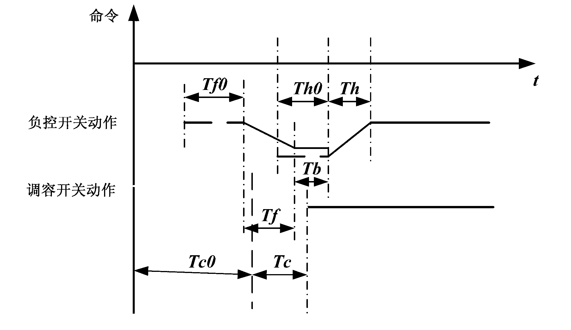
The invention provides an automatic capacity regulating distribution transformer and a capacity regulating method thereof. The distribution transformer comprises a transformer core, a capacity regulating switch, a load control switch and a comprehensive monitoring controller, and further comprises a transformer casing, wherein the capacity regulating switch and the load control switch are integrally designed and are suspended inside the transformer casing to be connected with the transformer core, the comprehensive monitoring controller is suspended out of the transformer casing, and is connected with the capacity regulating switch through a cable. The capacity regulating switch is composed of a permanent magnet operation mechanism and a disc-shaped switch, a fixed contact of the disc-shaped switch is connected with high and low voltage windings of the transformer core respectively, transformation of the low voltage winding is completed before the high voltage winding because the separated distances of a moving contact relative to the fixed contact are different during capacity regulating, so that currents born by a low voltage contact are reduced greatly, and ablation degree of the contact is alleviated; the comprehensive monitoring controller controls action sequences of a capacity adjusting negative control switch based on the action characteristics of the capacity regulating switch and the load control switch, capacity regulating is completed in an on-off period of the load control switch, and capacity changing time is shortened to be within 20ms.

Description

technical field [0001] The invention relates to the field of power distribution, in particular to an automatic capacity-adjusting power distribution transformer. Background technique [0002] There are two main disadvantages of the existing no-load capacity regulating transformers: one is that the capacity needs to be unloaded first and then manually adjust the capacity, which affects the reliability of power supply for users; The capacity adjustment basis for the next month lacks timeliness and scientificity, which may easily cause damage to the capacity regulating transformer and cannot give full play to the role of the capacity regulating transformer. [0003] The existing on-load capacity-regulating transformers realize on-load capacity-regulating through the on-load capacity-regulating switch, and the existing on-load capacity-regulating switches mostly use the motor rotation to drive the tap changer to realize the "Y-Δ" conversion and Low-voltage winding "series-paral...

Claims


Application Information

Patent Timeline
IPC IPC(8): H01F29/04H01F27/40H01H19/54H01H1/56G06F9/30
Inventor 魏贞祥杨福荣马振邦王海涛
Owner 北京博瑞莱智能科技集团有限公司
Learn More