
Shifting register unit, shifting register, display device and driving method

A technology for shift registers and storage capacitors, which is applied in the field of display devices, shift registers, and shift register units, and can solve the problems of the third thin film transistor M3 affecting the service life and the display panel display lines not working properly, etc.

Active Publication Date: 2012-10-03
BOE TECH GRP CO LTD +1
View PDF4 Cites 28 Cited by
  • Summary
  • Abstract
  • Description
  • Claims
  • Application Information

AI Technical Summary

Problems solved by technology

[0003] The embodiment of the present invention provides a shift register unit, a shift register, a display device and a driving method, which are used to solve the problem that the display lines below the display panel cannot work normally due to the superimposition of Delay in the existing shift register unit and The problem that the third thin film transistor M3 is often turned on and affects its service life

Method used


Image

  • Shifting register unit, shifting register, display device and driving method
  • Shifting register unit, shifting register, display device and driving method
  • Shifting register unit, shifting register, display device and driving method

Examples


Embodiment Construction

[0036] In order to make the technical problems, technical solutions and advantages to be solved by the embodiments of the present invention clearer, the following will describe in detail with reference to the drawings and specific embodiments.

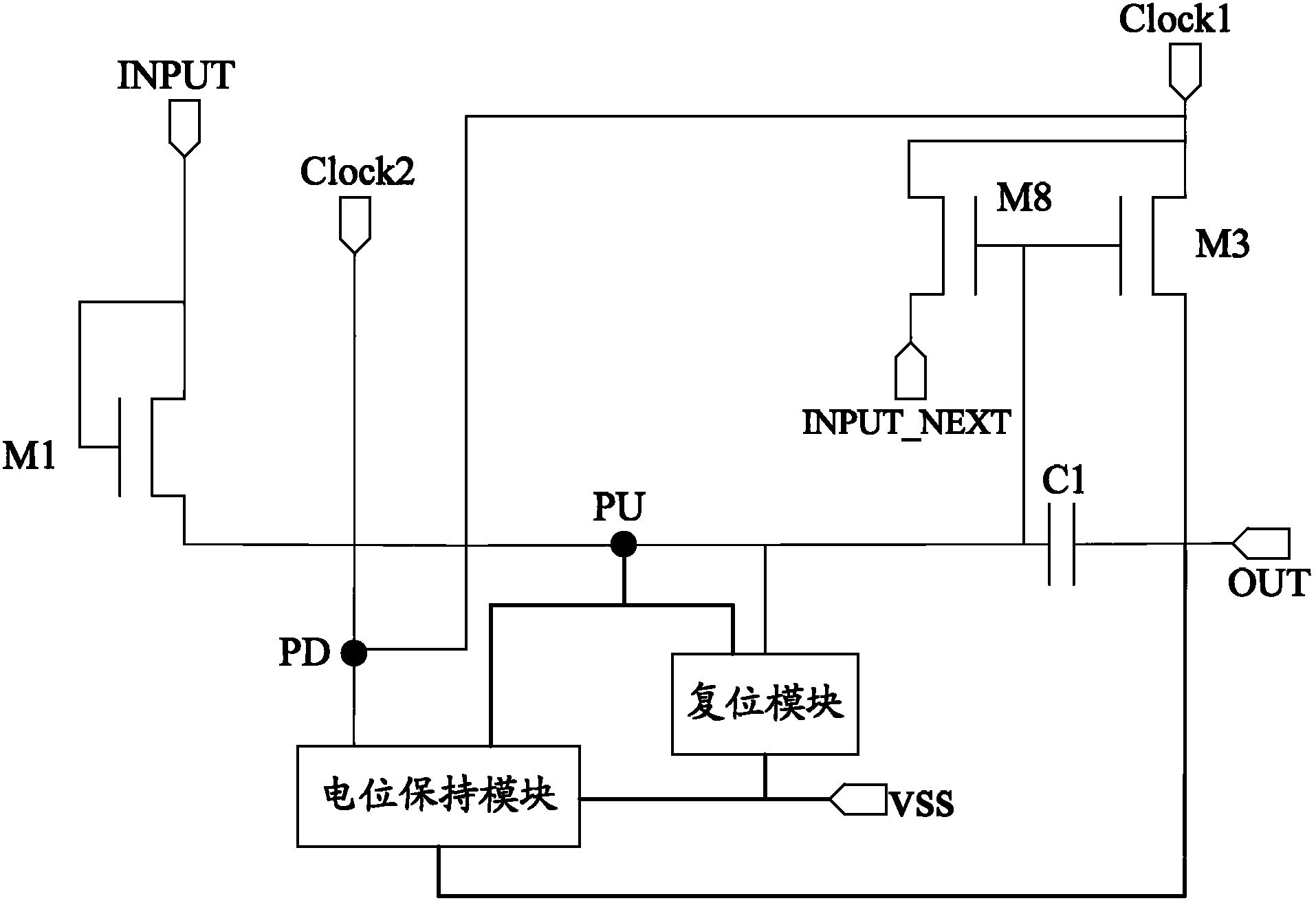
[0037] Such as figure 1 As shown, the embodiment of the present invention provides a shift register unit, including:

[0038] The first thin film transistor M1 is used to charge the pull-up node PU and the storage capacitor C1 when the input signal INPUT is at a high level; wherein, the input signal INPUT of this stage is input from the INPUT_NEXT terminal of the previous stage; preferably , when the eighth thin film transistor M8 is turned on, the first clock signal Clock1 is output to the INPUT_NEXT terminal through the eighth thin film transistor M8;

[0039] A reset module, configured to discharge the pull-up node PU and the storage capacitor C1 according to the control of the reset signal;

[0040] The third thin film transistor...


PUM


Abstract

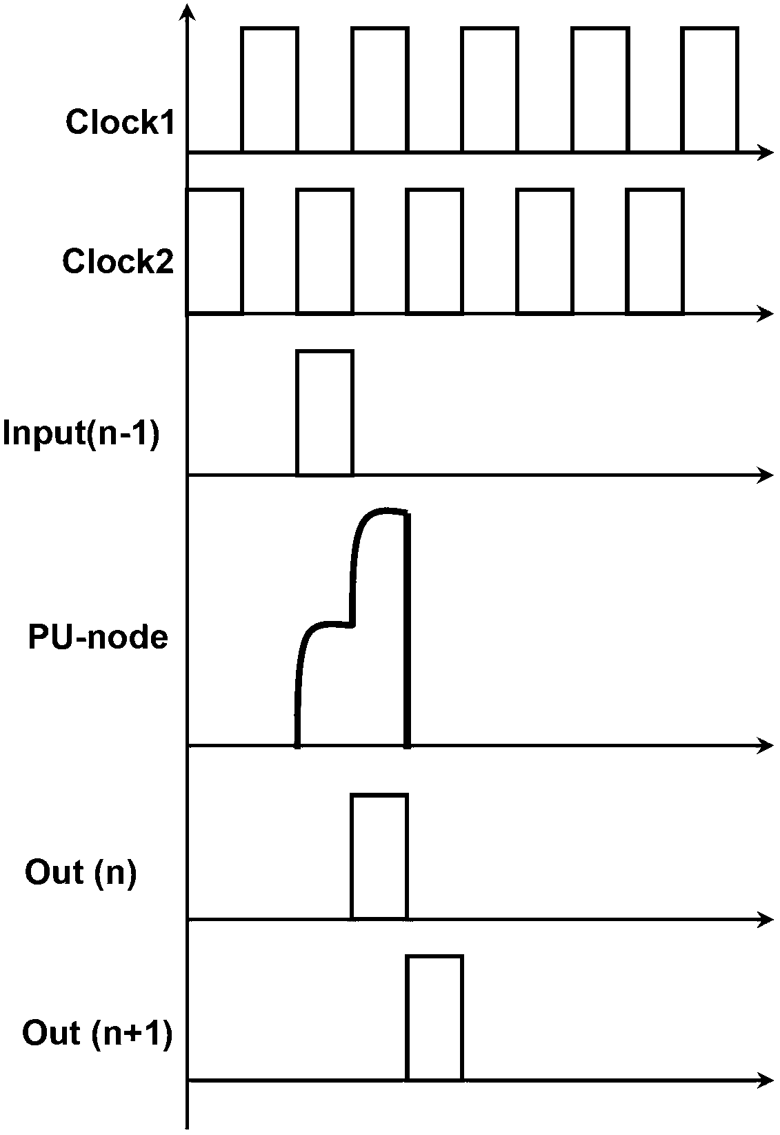
The invention provides a shifting register unit, a shifting register, a display device and a driving method, which are used for solving the problems that in a conventional shifting register unit, a display line below a display panel can not normally work due to the Delay overlap, and the service life of the conventional shift register is influenced caused by usually turning on a third thin film transistor M3. According to the technical scheme, an (n+1)th level of triggering signals are supplied by a first clock signal transmitted by an nth level of an INPUT_NEXT end, so that Delay caused by the triggering signals for the (n+1)th level, which is supplied by the nth level of OUT signals, can be avoided, and the problem that the display line below the display panel cannot normally work due to the Delay overlap can be solved. Furthermore, a pull-down node (PD) keeps a high level under the alternative control of two clock signals after the nth level outputs the OUT signals and before the next INPUT comes, so that a pull-up node (PU) and an output end can be ensured to continuously discharge, and the problem that the service life is influenced by usually turning on the M3 can be solved.

Description

technical field [0001] The invention relates to the technical field of display driving, in particular to a shift register unit, a shift register, a display device and a driving method. Background technique [0002] Amorphous silicon thin film transistor integrated gate drive (GOA) technology has gradually been applied in the field of TFT-LCD manufacturing, but in the process of continuous triggering of the existing GOA drive circuit, the trigger signal of the n+1th level is usually generated by The output signal of the Nth stage is provided, so that the Delay (delay) of the nth stage will be accumulated to the n+1th stage, causing the thin film transistor of the GOA drive circuit to realize the output function to not be turned on normally, and thus the resolution in the vertical direction is higher In the TFT-LCD panel and Dual Gate products, the lower display line may not work properly. In addition, due to the large size of the thin film transistor M3 that implements the m...

Claims


Application Information

Patent Timeline
IPC IPC(8): G11C19/28G09G3/36
CPCG11C19/28
Inventor 闫岩曹昆
Owner BOE TECH GRP CO LTD
Learn More