
Direct and integrated design method of band-pass filters

A band-pass filter and synthesis design technology, which is applied in the field of direct synthesis design of band-pass filters, can solve problems such as the inability to use comprehensive broadband filters, and achieve the effect of improving group delay characteristics

Inactive Publication Date: 2012-10-03
UNIV OF ELECTRONICS SCI & TECH OF CHINA
View PDF2 Cites 23 Cited by
  • Summary
  • Abstract
  • Description
  • Claims
  • Application Information

AI Technical Summary

Problems solved by technology

[0004] The purpose of the present invention is to overcome the deficiencies and defects that exist in the prior art, and solve the problems existing in the existing generalized Chebyshev single-pass band or multi-pass band band-pass filter synthesis design method, that is, the coupling matrix derived is only narrow-band Approximation, which cannot be used to synthesize wideband filters, proposes a direct synthesis design method for bandpass filters

Method used


Image

  • Direct and integrated design method of band-pass filters
  • Direct and integrated design method of band-pass filters
  • Direct and integrated design method of band-pass filters

Examples


Embodiment 1

[0083] Example 1: Synthesis of an eighth-order generalized Chebyshev single-passband filter

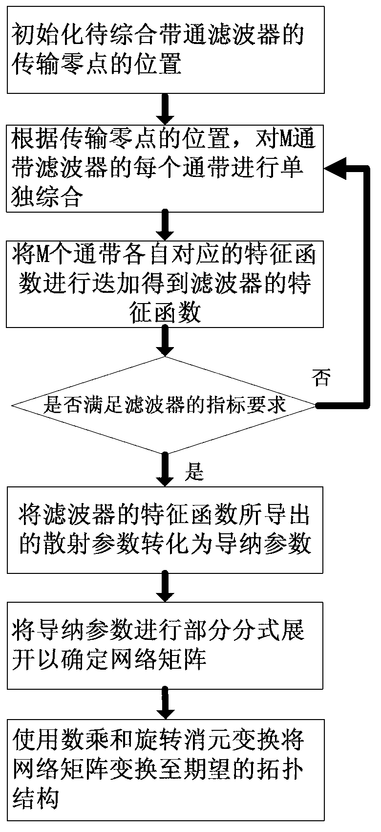
[0084] The passband of the filter is located at [4,6]GHz, and there is a transmission zero at zero frequency and infinity, and a transmission zero at 3.5GHz and 6.5GHz (the four transmission zeros are all pure imaginary numbers, using To control the amplitude response of the filter). The remaining four transmission zeros are all paired complex zeros, located in the passband, used to improve the group delay of the filter. Since the band synthesis filter is a single pass band filter, that is, M=1.

[0085] Using the method of the present invention, the eight transmission zero points adjusted in step S4 can be taken as: s ‾ 02 = j 3.5 , s ‾ 03 = 0.8 + j 4.65 , s ‾ 04 = - 0.8 + j 4.65 , s ‾ 05 = 0.77 + j 5.4 , s ‾ 06 = - 0.77 + j 5.4 , s ‾ 07 = j ...

Embodiment 2

[0105] Embodiment 2: Synthesis of a fourth-order generalized Chebyshev single-passband filter

[0106] The single-pass band filter comes from the literature: RJCameron, Advanced coupling matrix synthesis techniques for microwave filters, IEEE Transactions on Microwave Theory and Techniques, vol.51,no.1,Feb.2003,pp.1-10, through this Examples are given to illustrate the connection between the method of the present invention and existing methods.

[0107] The passband of this filter is located at [4.76,5.26]GHz (relative bandwidth is 8%), the first transmission zero is at 4.15GHz, the second is at 4.569GHz, the third is at 5.408GHz, and the fourth is at 6.779GHz , The return loss in the passband is 22dB. The network matrix derived according to the method of the present invention for:

[0108] [ A ‾ ] = - j 0.1739 0.3387 0.3222 0.1791 - 0.0145 0.1739 ω ‾ - 5.3360 0 0 0 0.1739 0.3387 0 ω ‾ ...

Embodiment 3

[0116] Embodiment 3: Synthesis of a fourth-order generalized Chebyshev double passband filter

[0117] The dual-passband filter comes from the literature: YTKuo and CYChang, Analytical design of two-mode dual-band filters using E-shaped resonators, IEEE Transactions on Microwave Theory and Techniques, vol. 60, no. 2, February 2012 ,pp.250-260. This example is used to illustrate the connection between the method of the present invention and the existing method.

[0118] The first passband of this filter is located at [1.64,1.76]GHz, and the second passband is located at [2.31,2.44]GHz. The four transmission zeros are located at 1.27GHz, 2.155GHz, 2.161GHz and 2.63GHz. The return loss in the passband is 20dB. The network matrix derived according to the method of the present invention for:

[0119] [ A ‾ ] = - j 0.1804 0.1937 0.1885 0.2053 - 0.2410 0.1804 ω ‾ - 1.5948 0 0 0 0.1804 0.1937 0 ...


PUM


Abstract

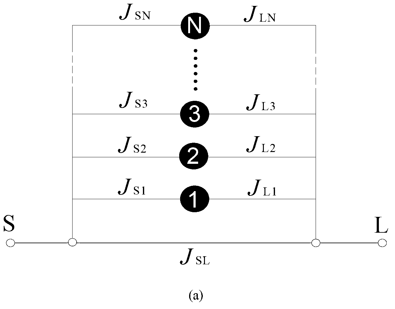
The invention discloses a direct and integrated design method of band-pass filters. In order to overcome the defect that the coupling matrix derived from the traditional integrated design method of the generalized Chebyshev single-pass-band or multi-pass-band band-pass filters is only narrow-band approximation and can not be used for integrated band-pass filters, the method is available for integrating the generalized Chebyshev single-pass-band or multi-pass-band band-pass filters in a band-pass domain directly, and improving the group delay characteristic in the pass band of the filter by introducing a plurality of transmission zeros. The direct and integrated design method can be used for extracting a network matrix of the generalized Chebyshev band-pass filters of the transmission zeros which have any bandwidth and are positioned at any frequency; and the derived network matrix has practical physical significance, while the network matrix derived from the traditional scheme can be taken as a low-pass narrow-band approximation result of the network matrix derived by using the method disclosed by the invention. The whole method disclosed by the invention has the advantages of simpleness, fastness and accuracy.

Description

Technical field [0001] The invention relates to a filter synthesis design method in the field of communication technology, in particular to a direct synthesis design method of a band pass filter. Background technique [0002] At present, the fields of mobile communication and wireless technology are in a period of rapid development. Various innovative mobile communication and wireless technologies continue to emerge and quickly enter commercial use. The application market is extremely active, and mobile and wireless technologies themselves are constantly innovating in rapid evolution. . As one of the indispensable key components in modern communication equipment, the radio frequency / microwave filter can effectively filter out various useless signals and noise signals, reduce signal interference between communication channels, and ensure the normal operation of communication equipment. Modern communication systems usually require filters to have good frequency selectivity and oth...

Claims


Application Information

Patent Timeline
IPC IPC(8): G06F17/50
Inventor 肖飞
Owner UNIV OF ELECTRONICS SCI & TECH OF CHINA
Learn More