
Winding device of roller shutters

A technology of roller blinds and roller blinds, which is applied to door/window protection devices, windows/doors, building components, etc. It can solve the problems of large outer diameter, large use space, and inflexible rotation, so as to achieve flexible rotation, Use effects with low noise and small footprint

Inactive Publication Date: 2012-10-03
SHANGHAI POWERWAY LOGISTICS EQUIP
View PDF0 Cites 0 Cited by
  • Summary
  • Abstract
  • Description
  • Claims
  • Application Information

AI Technical Summary

Problems solved by technology

[0004] like image 3 As shown, the existing roller blind winding device is mainly composed of a main support shaft 31 and a vortex spring 32 installed at both ends of the main support shaft 31. The elastic force of the vortex spring 32 is used to wind the roller blind. The roller blind exerts a pulling force to pull the roller blind out. The disadvantage of this winding device is that the shape of the vortex spring is similar to an involute, and its radial outer diameter is relatively large, so the entire device needs to occupy a large space for use, and Because the vortex spring is involute shape, when the rolling shutter piece rotates around the main support shaft, under the action of the vortex spring, there will be sliding friction between the inner and outer blades, which will generate a lot of noise, and the rotation will not be smooth. flexible

Method used


Image

  • Winding device of roller shutters
  • Winding device of roller shutters
  • Winding device of roller shutters

Examples


Embodiment Construction

[0014] The embodiments of the present invention will be described in further detail below in conjunction with the accompanying drawings, but the present embodiments are not intended to limit the present invention, and any similar structures and similar changes of the present invention should be included in the protection scope of the present invention.

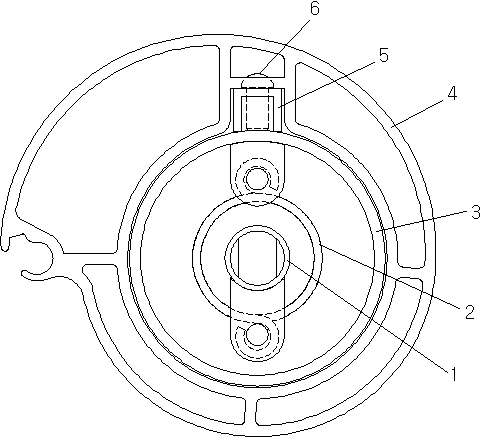
[0015] Such as Figure 1-Figure 2 As shown, a roller blind winding device provided by an embodiment of the present invention includes a main support shaft 1, the main support shaft 1 is a straight shaft, and a spring is provided at each of its left and right ends;

[0016] It is characterized in that: the outer peripheral coaxial sleeve of the main support shaft 1 is provided with a movable rotating cylinder 3, the rotating cylinder 3 is a straight cylinder, the two ends of which are respectively connected to the main supporting shaft 1 through bearings 7, and the outer walls of the two ends are respectively A shutter seat 4 f...


PUM


Abstract

The invention discloses a winding device of roller shutters, relates to the technical field of the roller shutters, and aims to reduce the space usage, improve the rotation flexibility and reduce the noise in use. The device comprises a main supporting shaft, wherein the main supporting shaft is a straight shaft; and a spring is sleeved on the left end and the right end of the main supporting shaft respectively. The device is characterized in that: a movable revolving drum is coaxially sleeved on the periphery of the main supporting shaft; the revolving drum is a straight drum of which the two ends are connected with the main supporting shaft through bearings respectively and the outer walls at the two ends are fixed with a roller shutter seat for fixing the roller shutters respectively; the springs are torsion springs; and one end of each torsion spring is fixedly connected with the main supporting shaft, and the other end of each torsion spring is fixedly connected with the revolving drum. The device provided by the invention is suitable for the roller shutter type doors and windows.

Description

technical field [0001] The invention relates to the technology of rolling blinds, in particular to the technology of a rolling device for rolling blinds. Background technique [0002] The rolling shutter door and rolling shutter window can make the door frame and window frame appear clean and tidy after being closed, and the operation is simple and convenient. It is widely used in building doors, windows, and cabinet and cabinet doors. [0003] Rolling shutter doors and rolling shutter windows are composed of rolling shutters and winding devices. The rolling shutters are connected sequentially from top to bottom by a number of parallel curtain leaves. Use the winding device to wind or release the rolling shutters to realize rolling shutters. (or window) opening and closing. [0004] Such as image 3 As shown, the existing roller blind winding device is mainly composed of a main support shaft 31 and a vortex spring 32 installed at both ends of the main support shaft 31. The ...

Claims


Application Information

Patent Timeline
IPC IPC(8): E06B9/56
Inventor 范进吴合永骆靓陈静李飞凡金章
Owner SHANGHAI POWERWAY LOGISTICS EQUIP
Learn More