
Foam system suitable for profile control and oil displacement of oil field and oil displacement method

A foam system and oil displacement technology, applied in chemical instruments and methods, production fluids, earthwork drilling, etc., can solve the problem of low oil displacement efficiency, reduce ineffective water circulation, improve oil displacement efficiency, and achieve good biodegradation. sexual effect

Active Publication Date: 2012-10-03
PETROCHINA CO LTD +1
View PDF7 Cites 43 Cited by
  • Summary
  • Abstract
  • Description
  • Claims
  • Application Information

AI Technical Summary

Problems solved by technology

This kind of foam system only has a good profile control effect, and its effect on improving oil displacement efficiency is small

Method used


Image

  • Foam system suitable for profile control and oil displacement of oil field and oil displacement method
  • Foam system suitable for profile control and oil displacement of oil field and oil displacement method
  • Foam system suitable for profile control and oil displacement of oil field and oil displacement method

Examples


Embodiment 1

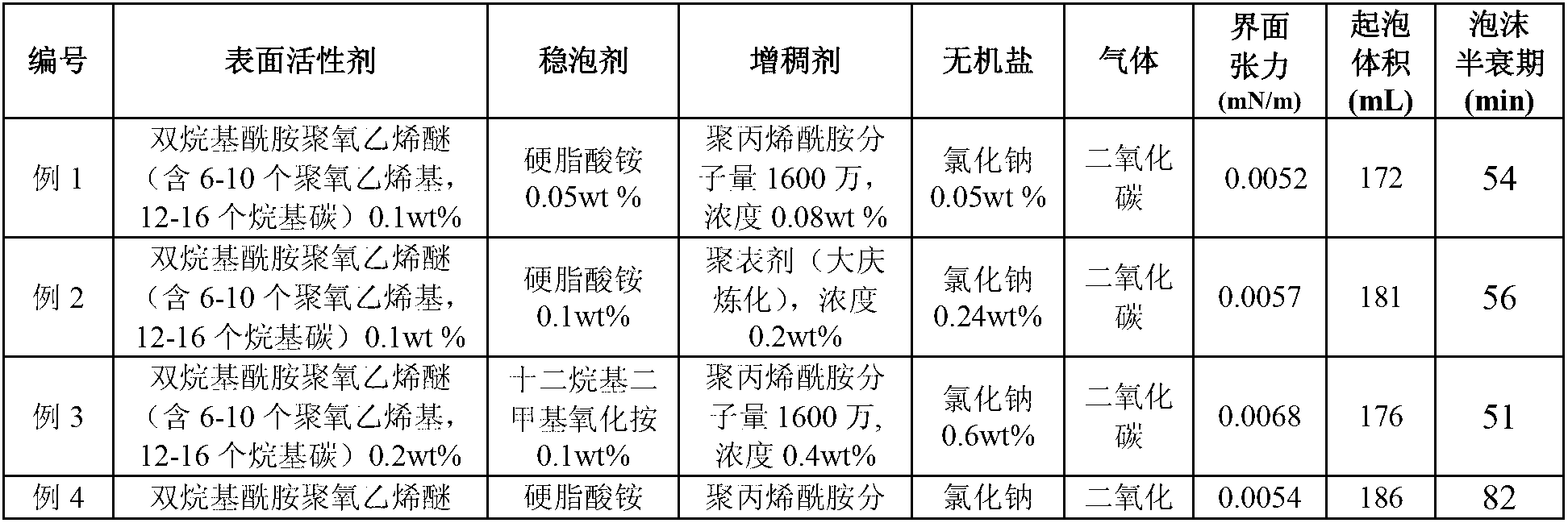
[0046] Embodiment one, the interface of foam system and foam performance

[0047] Table 1 provides specific examples 1-18 of foam systems suitable for oilfield profile control and oil displacement. The preparation method of the foam system is: dissolve the thickener in water at 45°C. Stir with a blender for 2 hours to completely dissolve and obtain a thickener solution. Add the inorganic salt to the thickener solution and stir it with a mixer for 0.5 hour to dissolve it completely. Then add the foam stabilizer and stir with a mixer for 0.5 hour to completely dissolve it. Finally, add the surfactant and dilute it with water to the target concentration, and stir slowly with a mixer for 0.5 hour to make it dissolve completely. Interfacial tension, foam volume and foam half-life were determined.

[0048] The US TX500C spinning drop interfacial tensiometer was used to measure the oil-water interfacial tension at 45°C and 4000 rpm. The oil used in the experiment was Daqing crude...

Embodiment 2

[0053] Example 2. Foam profile control and oil displacement effect

[0054] This embodiment provides a foam profile control flooding method, including water flooding and polymer flooding followed by a foam profile control flooding method.

[0055] (1) Foam profile control flooding experiment after water flooding:

[0056] (1) The man-made three-layer heterogeneous positive-rhythm core is selected, the size is 4.5cm×4.5cm×30cm, and the coefficient of variation of permeability is 0.72.

[0057] (2) Vacuumize the core to -1MPa at 45°C for two hours, inject water into the saturated oil field, and measure the pore volume of the core. Saturated Daqing Oilfield simulated oil (viscosity 9.5cp), determined oil saturation, and then aged for more than 12 hours.

[0058] (3) Water drive oil to 98% water cut, and determine water drive recovery.

[0059] (4) Foam profile control, foam injection method selection ①0.3PV foam system + 0.2PV polymer; ②0.05PV polymer + 0.3PV foam system + 0.1...


PUM


Abstract

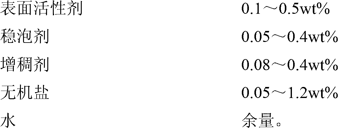
The invention relates to a foam system suitable for profile control and oil displacement of an oil field and an oil displacement method, in particular to a foam system formula used for profile control and oil displacement of the oil field after polymer flooding and a foam profile control oil displacement method. The foam system formula comprises in percentages by weight: 0.1-0.5 wt% of surfactant, 0.05-0.4 wt% of foam stabilizer, 0.08-0.4% of thickening agent, 0.05-1.2 wt% of inorganic salt and the balance of water. In the foam profile control oil displacement method, a ratio of gas to liquid of the foam system is as follows: the volume ratio of gas to liquid is 0.4: 1-1: 1 under an injection pressure. The foam system, provided by the invention, has super strong foam performance and ultra-low interface tension. The foam profile control effect is remarkable after polymer flooding, the yield is improved for more than 20%, and the economic benefit is remarkable.

Description

Technical field: [0001] The invention relates to a foam system formula for foam profile control and oil displacement in oil field development and a foam profile control and oil displacement method, in particular to a foam system formula for foam profile control and foam profile control after polymer flooding in an oil field Oil flooding method. technical background: [0002] The main reason for the profile control and oil displacement effect of foam is the seepage characteristics of foam in porous media, that is, the function of foam to block large but not small, water and not oil, which leads to uniform advancement of foam in high and low permeability layers. At the same time, the foam also has the effect of reducing the interfacial tension, so the foam has the effect of increasing the recovery factor. Under normal circumstances, the recovery rate can be increased by more than 30% after water flooding, and the recovery rate can be increased by 10-20% after polymer flooding...

Claims


Application Information

Patent Timeline
IPC IPC(8): C09K8/594E21B43/22
Inventor 韩培慧刘宏生许关利杨莉姜冬阳
Owner PETROCHINA CO LTD
Learn More