
Diluting type slurry tank and slurry tower stirrer

A technology of agitator and slurry tank, which is applied in the field of dilution type slurry tank slurry tower agitator, which can solve the problems of poor dilution and mixing effect, insufficient dilution, large flow loss, etc.

Active Publication Date: 2014-04-09
杭州萧山美特轻工机械有限公司
View PDF3 Cites 1 Cited by
  • Summary
  • Abstract
  • Description
  • Claims
  • Application Information

AI Technical Summary

Problems solved by technology

[0002] At present, most of the pulp tank pulp tower agitators used in the light industry and papermaking industry need to be used as the foundation, and are only suitable for circulating or stirring low-consistency pulp with a concentration below 6%. When the pulp concentration is higher than 6%, generally use indirect Dilution method, that is, it can only be diluted by pumping through the infusion pipes and valves on the surrounding wall of the slurry tank or slurry tower. The installation requires a certain height, nozzle size and quantity, and sealing, and the direction of the nozzles must be strictly controlled. Therefore, the dilution Only the slurry and its surface at the side wall of the slurry tank or the slurry tower have poor dilution and mixing effects, low circulation efficiency, high energy consumption for stirring, and certain installation difficulties
[0003] Although the dilution device is used in the patent ZL200420083729.1 "A Dilution Agitator", its conical dilution tube will generate a large vortex, the flow loss is large, and it can only reach a certain dilution area, and the dilution and mixing are not very uniform. And there is no dilution hole in the lower part, insufficient dilution, etc.

Method used


Image

  • Diluting type slurry tank and slurry tower stirrer
  • Diluting type slurry tank and slurry tower stirrer

Examples


Embodiment 1

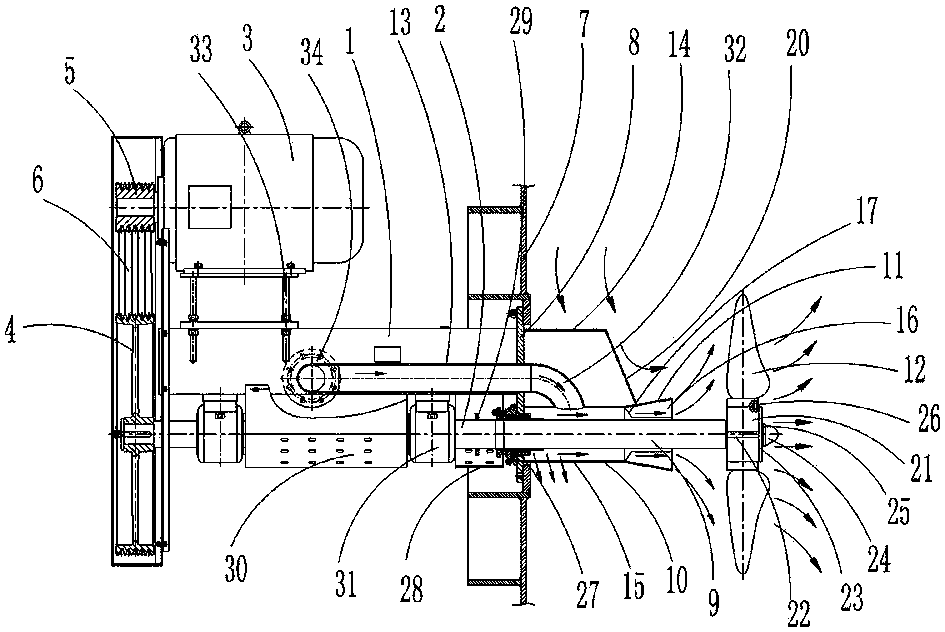
[0019] Embodiment 1: as figure 1 and figure 2 As shown, a dilution type slurry tank pulp tower agitator includes a base 1, a main shaft 2 is arranged in the base 1, a motor 3 is provided on the base 1, and the tail of the main shaft 2 A large pulley 4 is provided, and a small pulley 5 is provided on the motor 3. The small pulley 5 and the large pulley 4 are connected by a triangular tape 6. The motor 3 drives the main shaft 2 to rotate, and also includes a paddle Tower 7, the slurry tower 7 is fixedly connected with the base 1 through a connecting flange 8, the stirring section 9 at the head of the main shaft 2 in the base 1 extends into the slurry tower 7, and the stirring section 9 The outer jacket has a core dilution straight pipe 10 fixed to the inner wall of the slurry tower 7. The head of the core dilution straight pipe 10 is provided with a core liquid outlet reducer 11, and the head of the main shaft 2 is covered with Paddle 12, the base 1 is provided with an up...


PUM


Abstract

The invention relates to a stirrer, in particular to a diluting type slurry tank and slurry tower stirrer which is mainly used for diluting, mixing, circulating and stirring of slurry with medium and high concentration of 8-20% in the field of papermaking of light industries. A slurry tower is fixedly connected with a machine base through a connection flange, a stirring section on the head portion of a spindle in the machine base extends in the slurry tower, a core part diluting straight tube fixed with the inner wall of the slurry tower is sleeved outside the stirring section, a core part liquid outlet reducer is arranged on the head portion of the core part diluting straight tube, a slurry blade is sleeved on the head portion of the spindle, an upper diluting straight tube is arranged in the machine base and penetrates through the connection flange to extend into the core part diluting straight tube, a flow guiding cover is arranged above the core part diluting straight tube, and the upper diluting straight tube is communicated with the inside the slurry tower through the core part diluting straight tube and the core part liquid outlet reducer. The diluting type slurry tank and slurry tower stirrer is simple in structure, high in diluting performance, convenient and safe, reduces stirring energy consumption and improves circulating efficiency and operation stability.

Description

technical field [0001] The patent of the present invention relates to a stirrer, especially to a dilution type pulp tank pulp tower stirrer, which is mainly used for dilution, mixing, circulation and stirring of medium and high concentration pulp with a concentration of 8 to 20% in the light industry and papermaking industry, and is also suitable for on other similar occasions. Background technique [0002] At present, most of the slurry tank agitators used in the light industry and papermaking industry need to be used as the foundation, and are only suitable for circulating or stirring low-consistency pulp with a concentration below 6%. When the pulp concentration is higher than 6%, the indirect Dilution method, that is, it can only be diluted by pumping through the infusion pipeline and valves on the surrounding wall of the slurry tank or slurry tower. The installation requires a certain height, nozzle size and quantity, and sealing, and the direction of the nozzle must be...

Claims


Application Information

Patent Timeline
Patent Type & Authority Patents(China)
IPC IPC(8): B01F7/04B01F3/08
Inventor 戚加友严洪生
Owner 杭州萧山美特轻工机械有限公司
Learn More