
Clamping paw with centering function

A gripper and function technology, applied in the field of electronic component plug-in machine equipment, can solve the problems of no front-to-back alignment, lower gripping accuracy of the manipulator gripper, and higher rejection rate, and achieves the improvement of gripping accuracy and the simple and convenient control action. Effect

Inactive Publication Date: 2014-07-23
DONGGUAN SCIENCGO MACHINERY MFG
View PDF7 Cites 0 Cited by
  • Summary
  • Abstract
  • Description
  • Claims
  • Application Information

AI Technical Summary

Problems solved by technology

The manipulator claw in this technical solution can only realize the gripping function of the left and right sides. If the electronic component is not in the middle position of the manipulator claw during the clamping process of the electronic component, and the existing manipulator claw has no front-to-back centering function, As a result, the gripping accuracy of the manipulator claws is greatly reduced, and the scrap rate is high

Method used


Image

  • Clamping paw with centering function
  • Clamping paw with centering function
  • Clamping paw with centering function

Examples


Embodiment Construction

[0020] In order to facilitate the understanding of those skilled in the art, the present invention will be further described below in conjunction with the embodiments and accompanying drawings, and the contents mentioned in the embodiments are not intended to limit the present invention.

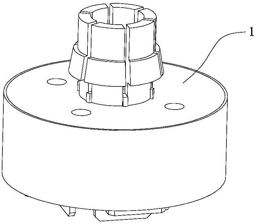
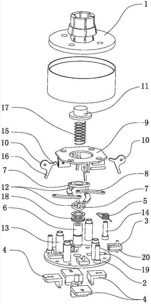
[0021] Such as Figure 1 to Figure 3 Shown is the first embodiment of the clamping gripper with the centering function of the present invention, which includes the gripper connecting cover 1 and the gripper body 2 arranged under the gripper connecting cover 1, and the middle part of the gripper connecting cover 1 is provided with a second A through hole, the claw body 2 is equipped with at least three radially movable claw sliders 3, and each claw slider 3 is equipped with a material clip 4; the side of the claw slider 3 A spring 5 is installed, and the two ends of the spring 5 are respectively connected with the gripper body 2 and the gripper slider 3; the middle part of the gripper body 2 ...


PUM


Abstract

The invention relates to the technical field of electronic component plug-in machines, in particular to a clamping paw with a centering function, The clamping paw with the centering function comprises a paw connecting cover and a paw body, wherein the paw body is arranged below the paw connecting cover; a first through hole is formed in the middle of the paw connecting cover; the paw body is equipped with at least three paw sliding blocks capable of moving in the radial direction; each paw sliding block is equipped with a material clamp; and in clamping, the at least three material clamps conduct the clamping from at least three different directions, so that electronic components are pushed to the center position of the clamping paw and then clamped, so as to overcome great defects that the conventional mechanical paw only conducts the clamping left and right, but the anteroposterior position of the component cannot be centered, and greatly improve the component clamping accuracy and the transporting position precision; in addition, all that is needed is to drive the linkage blocks to move up and down, the clamping and the releasing of the clamping paw can be realized, and the control action is simple and convenient.

Description

technical field [0001] The invention relates to the technical field of electronic component inserting machine equipment, in particular to a clamping gripper with a centering function. Background technique [0002] With the rapid development of the electronics industry, the application of electronic processing equipment is becoming more and more extensive, and the mechanical claw is a very commonly used device in electronic processing equipment. The mechanical claw is mainly used to pick up electronic components, and transport and install them on the circuit board. , but the existing manipulator claws have relatively high cost of processing equipment due to their complex structure and high difficulty in control. [0003] Chinese patent authorization announcement number CN 202162804U discloses a toggle-type mechanical gripper, including a gripper body and a material clamping mechanism, and the material clamping mechanism includes an elbow joint, two material clamping sliders, ...

Claims


Application Information

Patent Timeline
Patent Type & Authority Patents(China)
IPC IPC(8): B25J15/10
Inventor 梁发新高喜宏任明哲曾翔清陈卓标
Owner DONGGUAN SCIENCGO MACHINERY MFG
Learn More