Power tool

A technology of electric tools and tools, applied in the direction of manufacturing tools, portable mobile devices, metal processing equipment, etc., can solve the problem that the nut parts cannot be prevented from loosening, and achieve the effect of preventing loosening.

Inactive Publication Date: 2012-09-26
MAKITA CORP
View PDF7 Cites 6 Cited by
  • Summary
  • Abstract
  • Description
  • Claims
  • Application Information

AI Technical Summary

Problems solved by technology

[0008] If other inner parts are installed between the inner part with anti-off function and the disc-shaped tool by mistake, then, when the brake device works, the other inner parts will prevent the inner part with anti-off function from Disc-shaped tool moves sideways, which may cause loosening of nut parts that cannot be prevented

Method used


Image

  • Power tool
  • Power tool
  • Power tool

Examples


Embodiment Construction

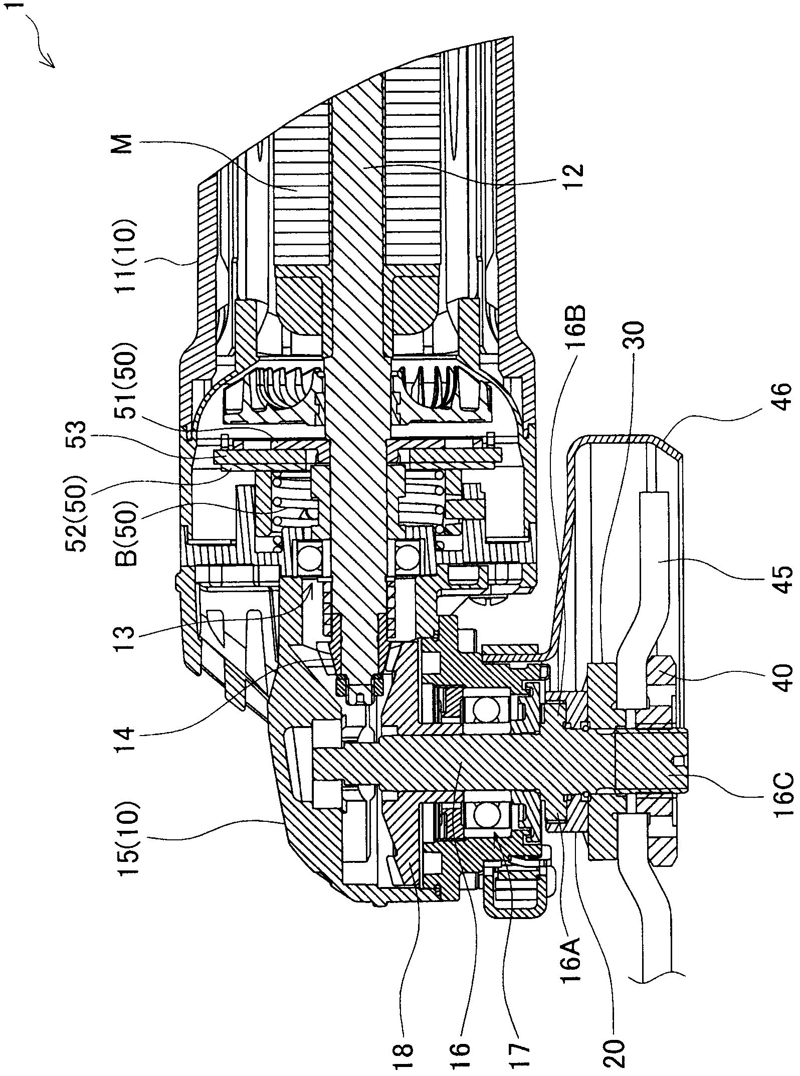
[0026] Refer below Figure 1 to Figure 6 Specific embodiments of the present invention will be described. Such as figure 1 As shown, the grinder 1 has a housing 10 , an anti-loosening component 20 , an inner flange 30 , a lock nut 40 , and a braking device 50 . In addition, the grinder 1 is an example of the electric tool of this invention.

[0027] The housing 10 is composed of a cylindrical motor housing 11 and a transmission mechanism housing 15 . The motor M is accommodated in the motor case 11 . A shaft 12 of the motor M is rotatably supported in the motor housing 11 via a bearing 13 . A first bevel gear 14 is provided at the head end of the rotating shaft 12 .

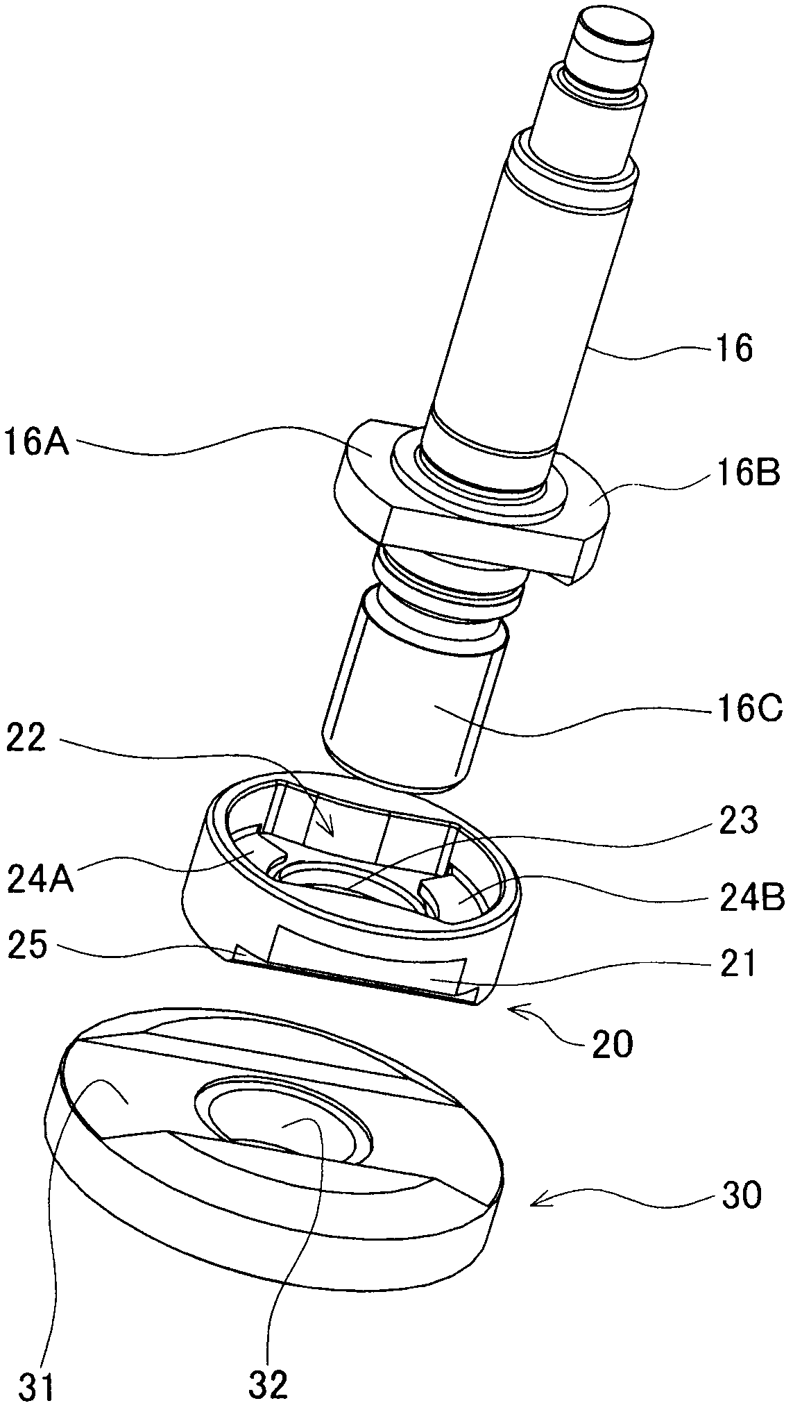
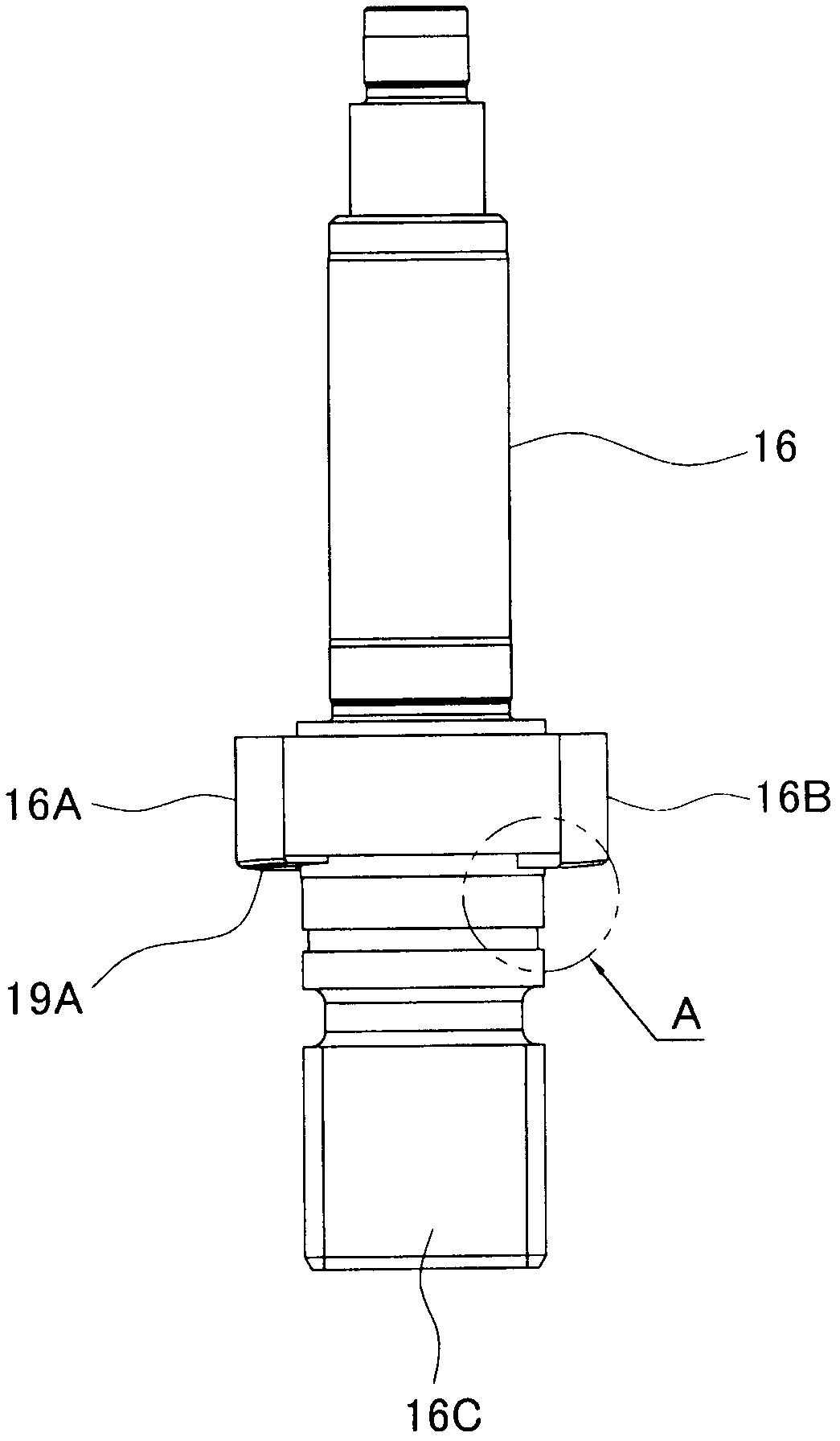
[0028] The transmission case 15 is assembled in front of the motor case 11 . The above-mentioned rotating shaft 12 extends from the motor housing 11 into the transmission mechanism housing 15 . A main shaft 16 is rotatably supported by a bearing 17 in the transmission case 15 , and the main shaft 16 is per...


PUM


Abstract

It is an object of the present invention to provide a power tool which is configured to prevent a nut member screwed on the spindle from loosening during operation of a brake device, when an inner member is mounted on the spindle. A grinder 1 comprises a main body (10) with a brake device (50), a spindle (16) provided with an inner member, integrally formed into a pressing portion and protruding from the main body. When the spindle is braked by the brake device, the inner member is pressed toward a tip end of the spindle by the pressing portion. The inner member comprises a locking member (20) that contacts the pressing portion and is pressed toward the disc-like tool (45) when the brake device (50) is operated, and an inner flange (30) which is detachably attached to the locking member (20) so as to be rotatable together with the locking member (20) and the disc-like tool is clamped between the inner flange and the nut member.

Description

technical field [0001] The present invention relates to an electric power tool, which has a main shaft, and a disc-shaped tool is mounted on the head end of the main shaft through a nut part. Background technique [0002] In general, a grinder as an example of an electric tool has a main shaft and a braking device for braking the main shaft, and a disc-shaped tool is attached to the head end of the main shaft protruding from the main body of the electric tool with a nut member. . However, on a grinding machine with a braking device, the nut part may be loosened when the braking device is working. In order to prevent such a problem, a technique is described in Patent Document 1: On the grinding machine of the device, the head end of the main shaft passes through the disc-shaped tool, and on the main shaft, a nut part is screwed on the main shaft head end side of the disc-shaped tool, and the main body side of the disc-shaped tool is equipped with a The inner part has the fu...

Claims


Application Information

Patent Timeline
Patent Type & Authority Applications(China)
IPC IPC(8): B25F5/00
CPCB24B23/028B24B45/00B24B23/02
Inventor 沼田文年
Owner MAKITA CORP
Why Eureka
Try Eureka