Multicolour light emitting diode lamp for use in plant cultivation, lighting device and plant cultivation method
A light-emitting diode lamp and technology of light-emitting diodes, which are applied in the directions of botanical equipment and methods, lighting devices, lighting devices, etc., can solve the problems of difficulty in practical application and high output power, and are not suitable for light sources, and achieve simplified lighting circuits, The effect of low cost, high output power
- Summary
- Abstract
- Description
- Claims
- Application Information
AI Technical Summary
Problems solved by technology
Method used
Image
Examples
no. 1 Embodiment approach >
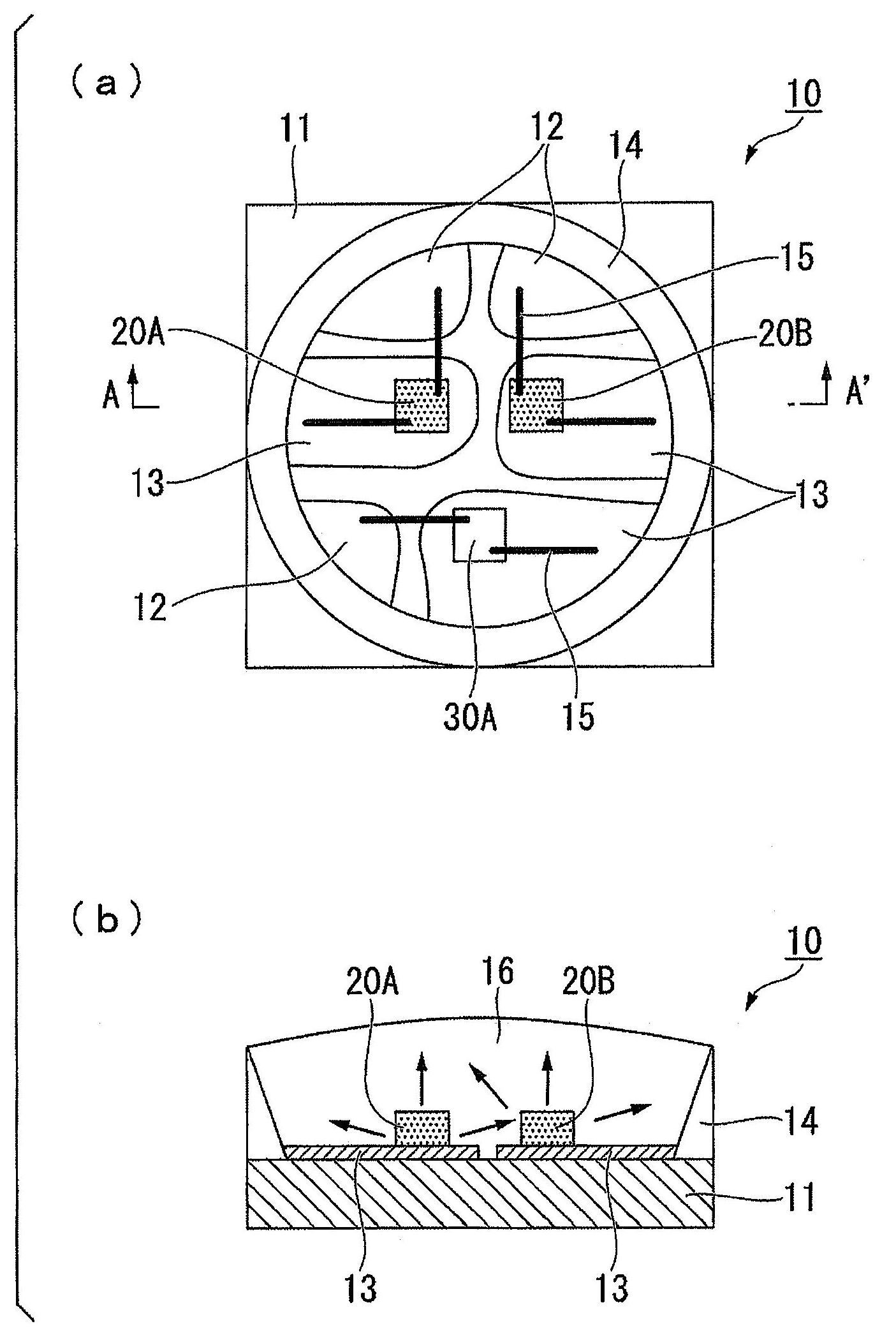
[0055] The configuration of a multicolor light-emitting diode lamp (hereinafter simply referred to as "light-emitting diode lamp") for plant cultivation as an embodiment to which the present invention is applied will be described.
[0056] like figure 1 (a) and figure 1 As shown in (b), the light emitting diode lamp 10 of this embodiment is schematically configured by mounting three light emitting diodes 20A, 20B, and 30A independently on the surface of the mounting substrate 11 . More specifically, the light emitting diodes 20A and 20B (first light emitting diodes) are red light emitting diodes with a peak emission wavelength of 655 nm to 675 nm, and the light emitting diode 30A (second light emitting diode) is blue light emitting diodes with a peak light emission wavelength of 420 nm to 470 nm. diode. (Red LED)
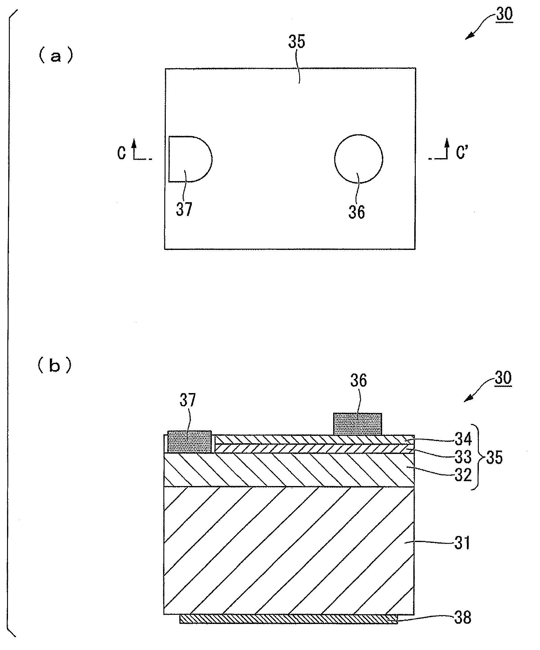
[0057] Here, the configuration of the red light emitting diodes 20A and 20B as the first light emitting diodes used in this embodiment will be described. figur...
no. 2 Embodiment approach >
[0140] Next, a second embodiment to which the present invention is applied will be described. In this embodiment, it has a structure different from the light emitting diode lamp 10 of 1st Embodiment. Therefore, regarding the configuration of the light emitting diode lamp of the present embodiment, the same components as those of the light emitting diode lamp 10 according to the first embodiment are denoted by the same symbols and description thereof will be omitted.
[0141] like Figure 5 (a) and Figure 5 As shown in (b), the light emitting diode lamp 210 of this embodiment is schematically configured by mounting five light emitting diodes 220A, 220B, 220C, 220D, and 230A on the surface of the mounting substrate 211 .
[0142] Here, the three light-emitting diodes 20A, 20B, and 30A mounted in the light-emitting diode lamp 10 of the first embodiment are electrically independent, but the light-emitting diode lamp 210 of the present embodiment, as Figure 5 (a) and Figure ...
no. 3 Embodiment approach >
[0152] Next, a third embodiment to which the present invention is applied will be described. In this embodiment, it becomes a structure different from the light emitting diode lamp 10,210 of 1st and 2nd embodiment. Therefore, regarding the configuration of the light emitting diode lamp of the present embodiment, the same components as those of the light emitting diode lamps 10 and 210 of the first and second embodiments are given the same symbols and their descriptions are omitted.
[0153] like Image 6 (a) and Image 6 As shown in (b), the light emitting diode lamp 310 of this embodiment is schematically configured by mounting five light emitting diodes 320A, 320B, 320C, 330A, and 330B on the surface of a mounting substrate 311 .
[0154] Here, the light-emitting diode lamps 10 and 210 of the first and second embodiments are driven by a DC power supply, but the light-emitting diode lamp 310 of the present embodiment is, for example, Image 6 (a) and Image 6 As shown in ...
PUM
 Abstract
Description
Claims
Application Information
 - R&D
- Intellectual Property
- Life Sciences
- Materials
- Tech Scout
- Unparalleled Data Quality
- Higher Quality Content
- 60% Fewer Hallucinations
Browse by: Latest US Patents, China's latest patents, Technical Efficacy Thesaurus, Application Domain, Technology Topic, Popular Technical Reports.
© 2025 PatSnap. All rights reserved.Legal|Privacy policy|Modern Slavery Act Transparency Statement|Sitemap|About US| Contact US: help@patsnap.com


