Optical fiber laser and cooling method thereof

A fiber laser and optical fiber technology, applied in the laser field, can solve the problems of slow heat dissipation, large heat dissipation, inconvenience of fiber lasers, etc., and achieve the effect of improving cooling efficiency and heat dissipation efficiency

Inactive Publication Date: 2012-09-19
MAXPHOTONICS CORP
View PDF6 Cites 4 Cited by
  • Summary
  • Abstract
  • Description
  • Claims
  • Application Information

AI Technical Summary

Problems solved by technology

[0003] At present, high-power fiber lasers with a power of more than 200 watts in the world cannot dissipate such a large amount of heat in a short period of time due to forced air cooling, so they basically use ordinary water cooling methods, that is, the pump source, beam combiner, Optical components such as fiber gratings, rare earth-doped active double-clad fibers, and fusion splice protection points are installed on a high-precision, high-flatness metal base plate, and cooling water or cooling liquid is passed through the lower part of the metal base plate. The heat generated by the device first conducts the heat to the metal base plate through contact heat transfer and radiation heat transfer, and the metal base plate then transfers the heat to the circulating cooling water and is taken away by the cooling water. This method has a better heat dissipation effect than forced air cooling. It is good, but the heat dissipation efficiency is still not ideal, and the heat dissipation speed is not fast, which limits the possibility of further increasing the output power of fiber lasers
[0004] In summary, there are obvious inconveniences and defects in the actual use of existing fiber lasers, so it is necessary to improve

Method used


Image

  • Optical fiber laser and cooling method thereof
  • Optical fiber laser and cooling method thereof
  • Optical fiber laser and cooling method thereof

Examples


Embodiment Construction

[0028] In order to make the object, technical solution and advantages of the present invention clearer, the present invention will be further described in detail below in conjunction with the accompanying drawings and embodiments. It should be understood that the specific embodiments described here are only used to explain the present invention, not to limit the present invention.

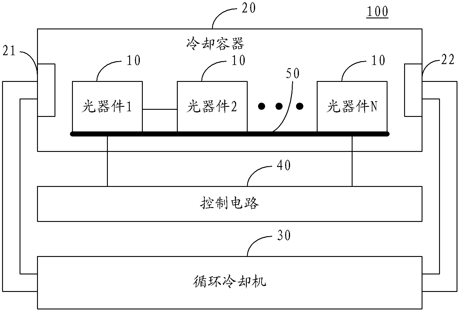
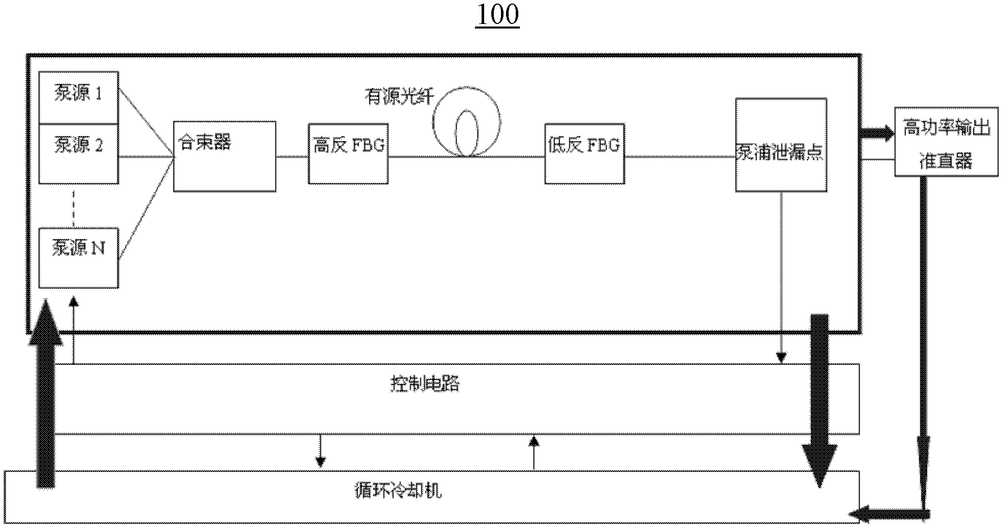
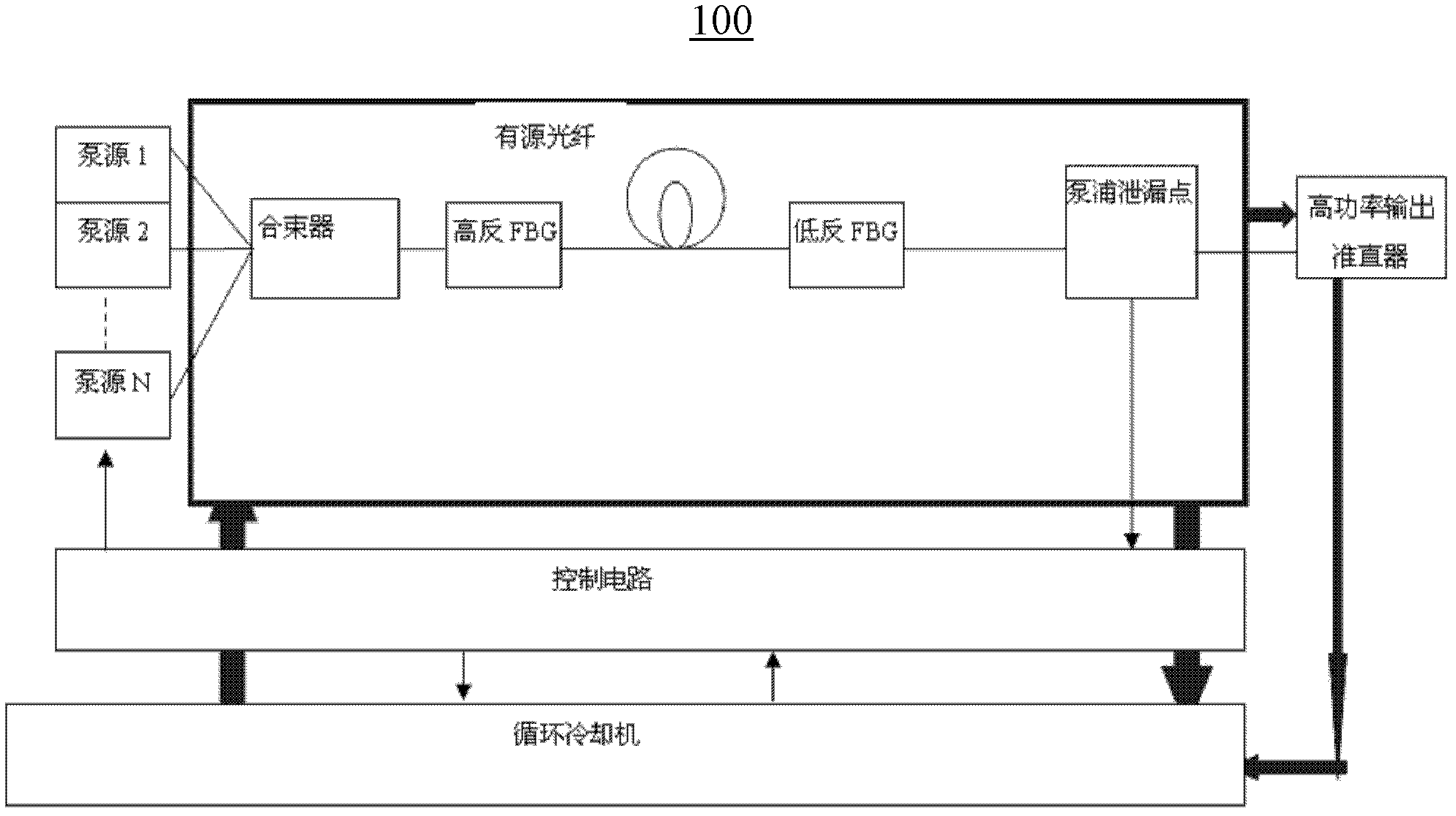
[0029] figure 1 It is a structural schematic diagram of the fiber laser of the present invention. The fiber laser 100 includes several optical devices 10, a cooling container 20, a circulating cooler 30 and cooling liquid. The optical device 10 may include several pump sources, a beam combiner, and a fiber grating , active optical fiber, fusion splicing point, pump leakage point and / or passive optical fiber and other high-power optical devices, and the optical device 10 is partially or completely installed in the cooling container 20, and the passive optical fiber and active optical fiber are Doub...


PUM


Abstract

The invention provides an optical fiber laser which comprises a plurality of optical devices, a cooling container, a circulating cooler and cooling liquid. The optical devices are arranged in the cooling container; the cooling container comprises a liquid inlet and a liquid outlet; the liquid inlet and the liquid outlet are respectively connected with the circulating cooler; the cooling liquid flows into the cooling container through the circulating cooler and the liquid inlet, so that the optical devices in the cooling container are soaked in the cooling liquid; and after flowing through the optical devices in the cooling container, the cooling liquid flows back into the circulating cooler through the liquid outlet. Correspondingly, the invention also provides a cooling method of the optical fiber laser. Therefore, according to the invention, the cooling efficiency of the optical fiber laser can be greatly improved, so that the output power of the optical fiber laser can be further improved.

Description

technical field [0001] The invention relates to the field of laser technology, in particular to a fiber laser and a cooling method thereof. Background technique [0002] The technical difficulty of fiber lasers, especially high-power fiber lasers with a power of several hundred watts to 10 kilowatts, lies in the thermal management of the entire fiber laser and unit optical devices. Taking a pulsed fiber laser with a power of 1KW as an example, if the output power It is 1000 watts, calculated according to the light-to-light conversion efficiency of 70%, the effective pump light power is (1000W÷70%=about 1428.6W), calculated according to the loss of 5% beam combiner, the pump before entering the beam combiner The pump light power is (1428.6W÷95%=about 1503.8W), calculated according to the 50% electro-optical conversion efficiency of the pump laser, the electric power to be provided is (1503.8÷50%=3007.5W or so), and because the fiber laser is still There are driving circuits,...

Claims


Application Information

Patent Timeline
Patent Type & Authority Applications(China)
IPC IPC(8): H01S3/042H01S3/067
Inventor 胡小波
Owner MAXPHOTONICS CORP
Why Eureka
Try Eureka