
Radio frequency identification (RFID) sensing tag system for monitoring storage device status

A technology of sensing tags and storage devices, which is applied in the field of RFID sensing tag systems based on active RFID technology, can solve the problem that the light sensing tag does not work, the electronic tag can no longer operate normally, and cannot know that it has been opened. Time and other issues, to achieve the effect of easy real-time monitoring, long-lasting use, and less use restrictions

Inactive Publication Date: 2012-09-19
HESHAN ASTROS PRINTING
View PDF6 Cites 11 Cited by
  • Summary
  • Abstract
  • Description
  • Claims
  • Application Information

AI Technical Summary

Problems solved by technology

[0005] The anti-tampering electronic tag is an electronic tag with a weakened line. When using it, it needs to be pasted on the opening of the storage device. Once the storage device is illegally opened, the electronic tag will also be damaged along the weakened line, so that the electronic tag can no longer work normally. Infer that the corresponding storage device has been tampered with
Although the anti-tampering electronic tag can detect the illegal opening of the storage device, it cannot know the time of opening and cannot monitor in real time, and the electronic tag will eventually be damaged due to the normal opening of the storage device, so each electronic tag can only be used once
Although the use of light-sensing tags can record time and achieve real-time monitoring, but for illegal opening in the dark, the light-sensing tags will not play a role

Method used


Image

  • Radio frequency identification (RFID) sensing tag system for monitoring storage device status
  • Radio frequency identification (RFID) sensing tag system for monitoring storage device status
  • Radio frequency identification (RFID) sensing tag system for monitoring storage device status

Examples


Embodiment Construction

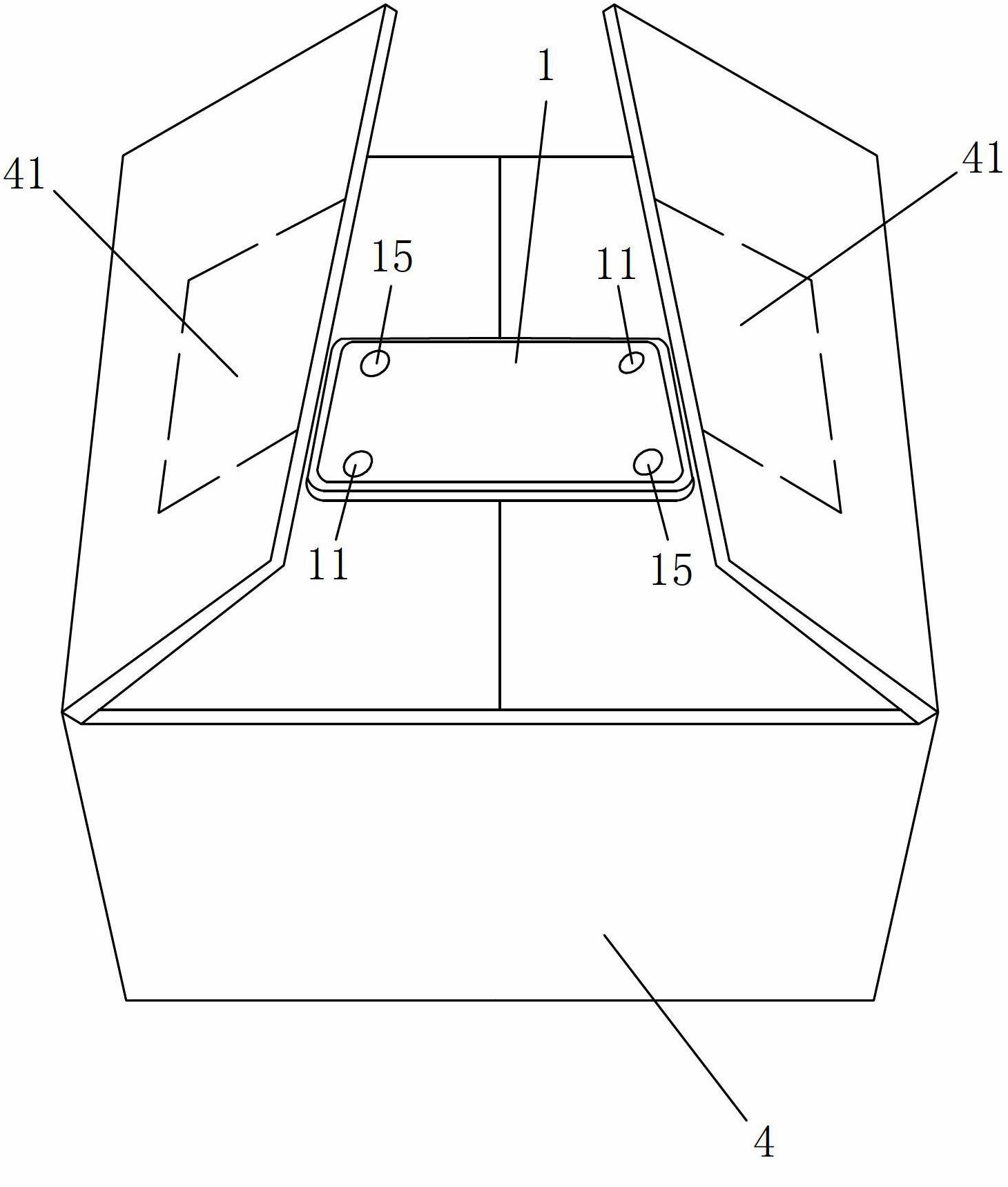
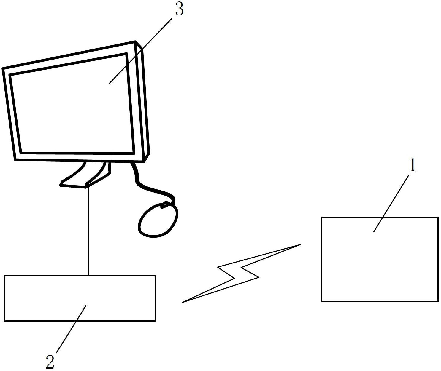
[0029] Reference figure 1 with image 3 As shown, an RFID sensor tag system for monitoring the state of the storage device of the present invention includes an RFID sensor tag 1, a sensor tag receiver 2 for detecting the status of the storage device 4, and a sensor tag 1 The monitored computer 3, the RFID sensor tag 1 is arranged on the storage device 4 and is wirelessly connected to the sensor tag receiver 2, and the sensor tag receiver 2 is wired or wirelessly connected to the computer 3.

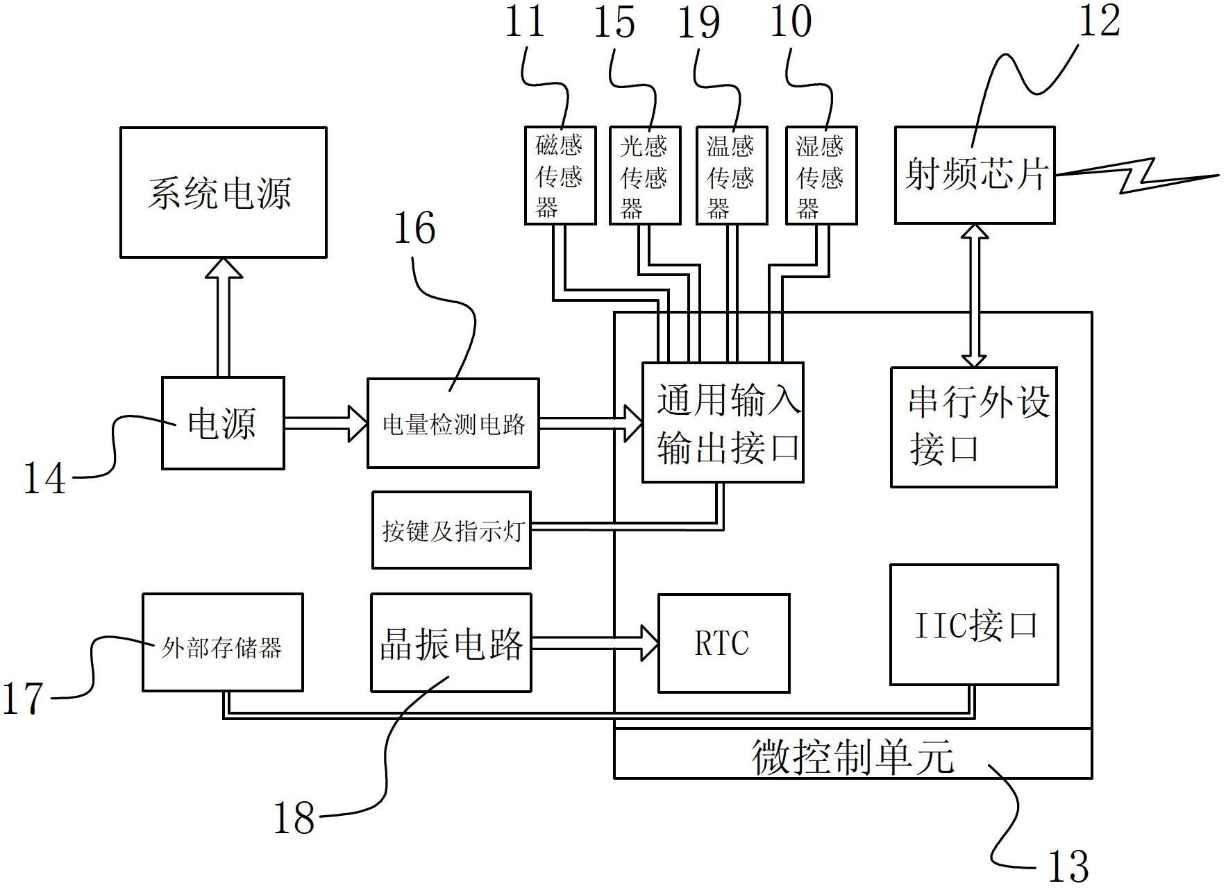
[0030] Reference figure 2 As shown, the RFID sensor tag 1 includes a magnetic sensor 11 that knows the storage status of the storage device 4 by detecting the value of the magnetic field, a radio frequency chip 12 for sending and / or receiving wireless signals, a micro-control unit 13 and a circuit Provide a power supply 14 for power supply. The magnetic sensor 11 is connected to the micro control unit 13 through a universal input and output interface. The radio frequency chip 12 is connected...


PUM


Abstract

The invention discloses an RFID sensing tag system for monitoring storage device status. The system comprises an RFID sensing tag, a sensing tag receiver and a computer, wherein the RFID sensing tag comprises a magnetic induction sensor, a radio frequency chip, a micro control unit and a power supply, the radio frequency chip is used for sending and / or receiving wireless signals, the power supply is used for supplying power to a circuit, the magnetic induction sensor, the radio frequency chip and the power supply are respectively connected with the micro control unit, and an opening position on a storage device, which corresponds to the magnetic induction sensor, is coated with magnetic materials or a magnet is embedded in the opening position. By the aid of the system, real-time monitoring of the storage status of the storage device can be achieved, and the magnetic induction sensor is used for detecting the status of the storage device, so that the RFID sensing tag of the system can be used repeatedly, the system is very environment-friendly, and real-time monitoring can be achieved easily. The system is less in usage limit, wide in application range and applicable to various storage environments and various storage devices.

Description

Technical field [0001] The invention relates to an RFID sensor label system for monitoring the state of a storage device, in particular to an RFID sensor label system based on active RFID technology applied to the fields of security, logistics and transportation, and confidential document storage. Background technique [0002] With the development of electronic tags and sensor technologies, electronic tags can not only be attached to the items to be identified as electronic marks for the items to be identified, but also can be combined with sensors as a tool to monitor the state of the item storage device, such as using electronic tags and temperature sensors To monitor the temperature status of the food freezer or use electronic tags and humidity sensors to monitor the humidity status of the drug warehouse. The sensor tag converts the special physical state change signal detected by the sensor on the tag into a digital signal and sends it through radio frequency technology; the ...

Claims


Application Information

Patent Timeline
Patent Type & Authority Applications(China)
IPC IPC(8): G06K17/00
Inventor 梁延国
Owner HESHAN ASTROS PRINTING
Learn More