Array substrate, manufacture method thereof, display panel and display device
A technology for array substrates and display panels, applied in semiconductor/solid-state device manufacturing, instruments, semiconductor devices, etc., can solve problems such as increased cost, weakened electromagnetic wave intensity, and reduced spatial magnetic flux rate of change.
- Summary
- Abstract
- Description
- Claims
- Application Information
AI Technical Summary
Problems solved by technology
Method used
Image
Examples
Embodiment 1
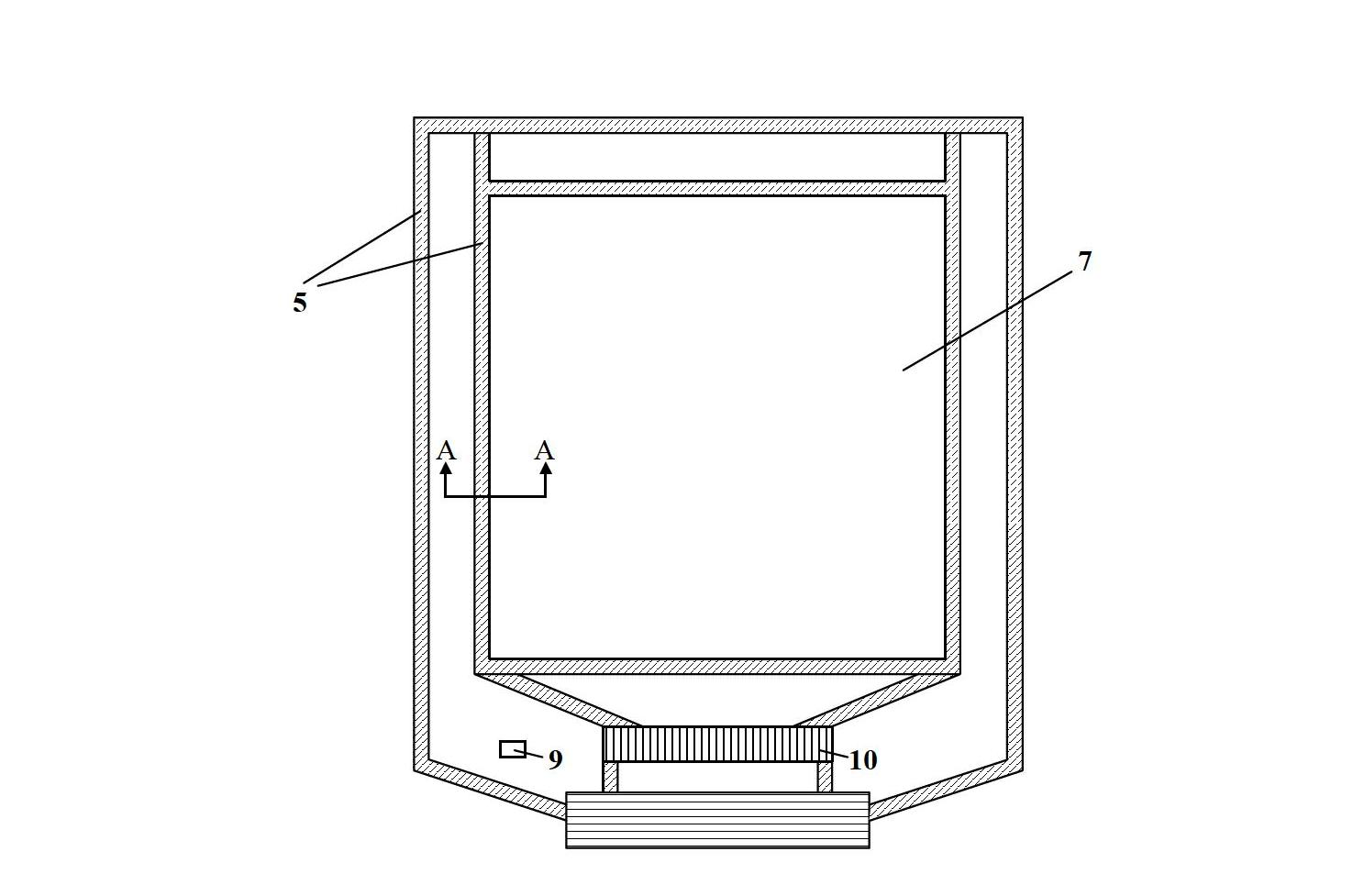
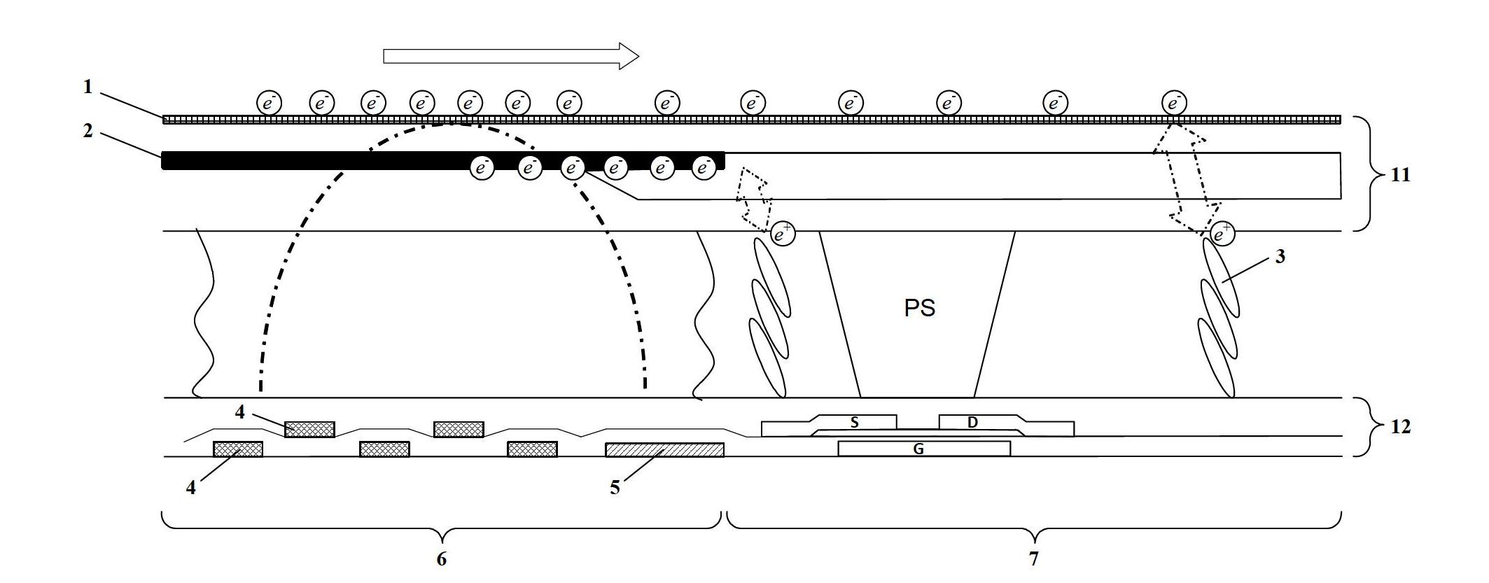
[0040] In this embodiment, the array substrate includes a plurality of gate lines, a plurality of data lines, a common electrode and a shielding layer. Wherein, each gate line and data line includes an outer lead, which are respectively called the outer lead of the gate line and the outer lead of the data line, and the number of the outer lead of the gate line is the same as that of the gate line, and the outer lead of the data line is the same as the number of the data line. The same number; the common electrode includes a plurality of outer leads, called the outer leads of the common electrode.
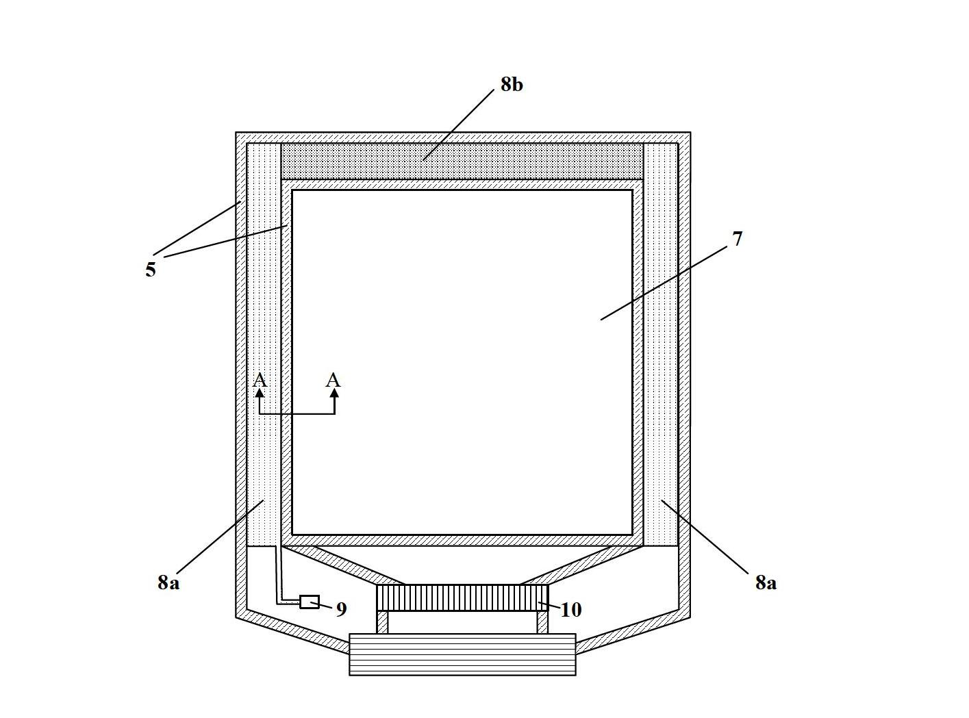
[0041] The shielding layer is arranged above the outer leads of the plurality of grid lines and connected to the grounding point, and is used for shielding space electromagnetic wave radiation excited by voltage changes in the outer leads of the plurality of grid lines. Preferably, the shielding layer covers the outer leads of the plurality of gate lines, and the shielding layer and...
Embodiment 2
[0056] The difference between this embodiment and Embodiment 1 is that in this embodiment, the array substrate does not include the connection layer 8b, and the shielding layer 8a is respectively arranged on the left and right sides of the effective display area 7 above the outer leads 4 of the plurality of gate lines. Connect to two ground points respectively.
[0057] Other structures, methods, and functions in this embodiment are the same as those in Embodiment 1, and will not be repeated here.
Embodiment 3
[0059] Such as Figure 5 As shown, the difference between this embodiment and Embodiment 1 is that in this embodiment, the connection layer 8b is disposed above the outer leads of multiple data lines. Specifically, the connection layer 8b is disposed above the outer leads of the multiple data lines located at the bottom of the effective display area 7, that is, the shielding layer 8a and the connection layer 8b form a U-shaped structure.
[0060] Preferably, the connection layer 8b covers the outer leads of the plurality of data lines, and the connection layer 8b and the outer leads of the plurality of data lines are not electrically connected to each other. Further preferably, the insulating layer in the array substrate is also disposed between the connection layer 8b and the outer leads of the multiple data lines, so that the connection layer 8b and the outer leads of the multiple data lines are not electrically connected to each other.
[0061]In this embodiment, the width...
PUM
 Abstract
Description
Claims
Application Information
 - R&D
- Intellectual Property
- Life Sciences
- Materials
- Tech Scout
- Unparalleled Data Quality
- Higher Quality Content
- 60% Fewer Hallucinations
Browse by: Latest US Patents, China's latest patents, Technical Efficacy Thesaurus, Application Domain, Technology Topic, Popular Technical Reports.
© 2025 PatSnap. All rights reserved.Legal|Privacy policy|Modern Slavery Act Transparency Statement|Sitemap|About US| Contact US: help@patsnap.com


