
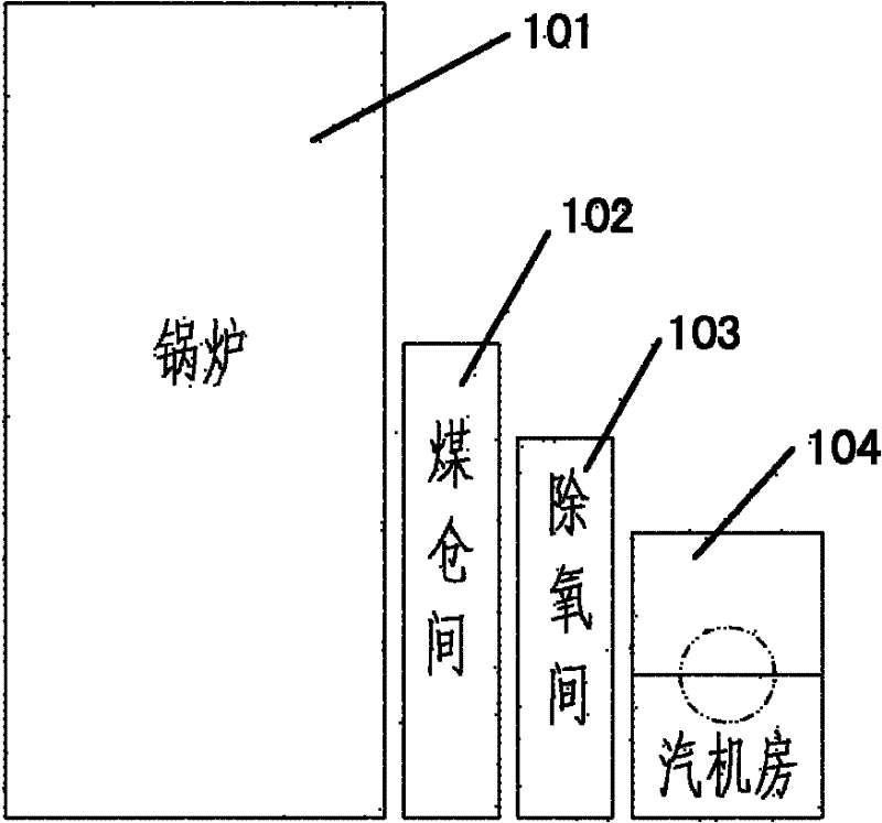
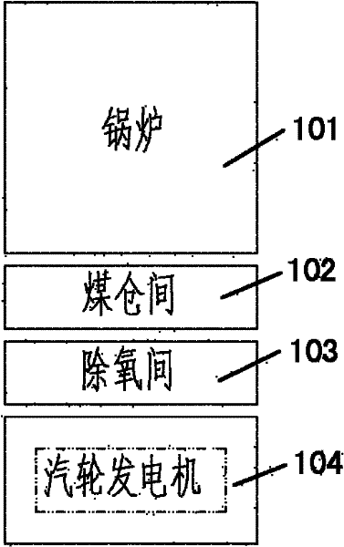
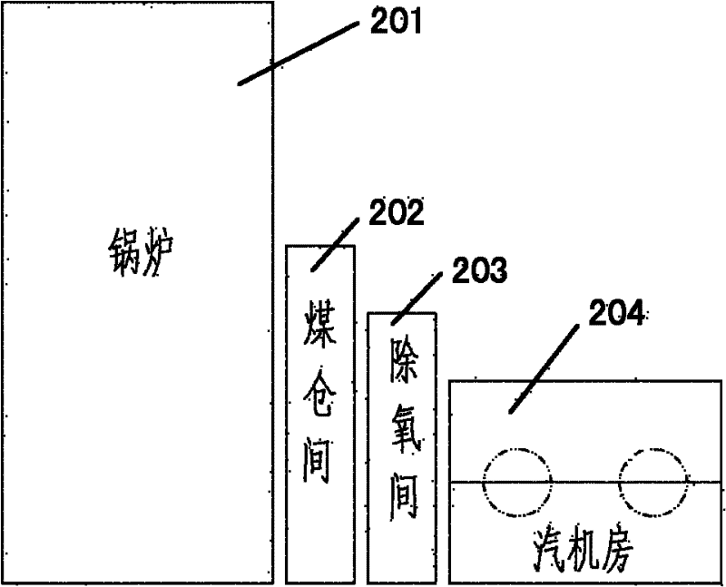
Main plant with steam turbine generator arranged on high level

A technology of steam turbine generator and steam turbine generator set, which is applied in industrial buildings and other directions, can solve the problems of reducing the cost of high-temperature piping, increasing the cost of civil construction, and long distance of high-temperature interfaces, and achieves improved normal operation efficiency and good investment income. , the effect of shortening the distance between the high temperature interface

Inactive Publication Date: 2012-09-19
CHINA POWER ENG CONSULTING GRP CORP EAST CHINA ELECTRIC POWER DESIGN INST
View PDF3 Cites 5 Cited by
  • Summary
  • Abstract
  • Description
  • Claims
  • Application Information

AI Technical Summary

Problems solved by technology

[0008] The high-level layout of the main workshop of the steam turbine generator proposed by the present invention is aimed at the large height difference between the low-level layout of the steam turbine generator and the boiler, which leads to long distances between the high-temperature interface between the steam turbine and the boiler, long piping systems, high investment, and low flow rate. Due to the problem of large resistance and low efficiency, and the high cost of the steel structure of the turbine room arranged on the boiler, etc., all or part of the shafting of the turbine generator is installed in the deaeration room and ( Or) the upper part of the frame formed by merging the coal bunkers, the cost of the civil structure increases less, while the cost of the high-temperature piping system is greatly reduced, and the normal operation efficiency is improved, so that it has a better return on investment

Method used


Image

  • Main plant with steam turbine generator arranged on high level
  • Main plant with steam turbine generator arranged on high level
  • Main plant with steam turbine generator arranged on high level

Examples


Embodiment Construction

[0038] The embodiments of the present invention will now be described in detail with reference to the drawings.

[0039] Figure 3a with Figure 3b It shows the main building of the single-shaft high-position turbine generator according to the present invention.

[0040] In this embodiment, the main plant of the high-level arrangement of the steam turbine generator of the present invention mainly includes: a boiler room 301, a deaeration coal bunker integrated frame 302, and a high-level turbine room 303. The deaeration coal bunker integrated frame 302 is composed of a combination of a deaeration room and a coal bunker room and is arranged next to one side of the boiler 301. In addition, as shown in the figure, the high-level steam engine room 303 is installed on the upper part of the integrated frame 302 of the deaeration coal bunker. The single-shaft steam turbine generator is arranged in the high-level turbine room 303. The base can be arranged on the main beam of the integrat...


PUM


Abstract

The invention provides a main plant with a steam turbine generator arranged on high level. The main plant comprises a boiler room, a deoxidizing bunker integrated frame and a high-level steam turbine room, wherein the deoxidizing bunker integrated frame consists of a deoxidizing room and a bunker room, which are adjacently arranged on one side of a boiler; and the high-level steam turbine room is arranged at the upper part of the deoxidizing bunker integrated frame. According to the main plant with the steam turbine generator arranged on high level disclosed by the invention, the shaft system of the steam turbine generator is fully or partially arranged at the upper part of the frame which is formed by combining the deoxidizing room and (or) the bunker room, so that the cost of a civil engineering structure is slightly increased, the cost of a high-temperature pipe system is greatly reduced, the normal operation efficiency is improved, and better investment return rate is achieved.

Description

Technical field [0001] The invention relates to the field of construction of thermal power plants, in particular to a main plant with a high-position steam turbine generator. Background technique [0002] In conventional thermal power plants, due to the large size of the steam turbine generator and the heavier equipment, the base is usually arranged on the basis of connection with the ground. In this way, the cost of the civil structure can be relatively low. In the equipment layout of the main plant, the steam turbine generator is arranged at a lower position in a separate turbine room. However, because the boiler is relatively tall, and the main piping interface of the main steam and reheat of the boiler is located on the upper part of the boiler, the main piping system of main steam and reheat connected between the boiler and the turbine has a longer length. The cost is high; and the piping system is longer, which will increase the flow resistance and reduce the economy of no...

Claims


Application Information

Patent Timeline
IPC IPC(8): E04H5/02
Inventor 陈仁杰叶勇健林磊申松林沈凤英施刚夜范沁蒋健
Owner CHINA POWER ENG CONSULTING GRP CORP EAST CHINA ELECTRIC POWER DESIGN INST
Learn More