Built-in and suspension integrated hub motor drive electric wheel
An in-wheel motor and integrated technology, applied in the direction of motors, electric vehicles, electric components, etc., can solve the problems of inability to realize the inner rotor structure scheme, increase the variation of the motor magnetic gap, and affect the performance of the motor torque, so as to improve the dynamics characteristics, improved vibration characteristics, and improved service life
- Summary
- Abstract
- Description
- Claims
- Application Information
AI Technical Summary
Problems solved by technology
Method used
Image
Examples
Embodiment 1
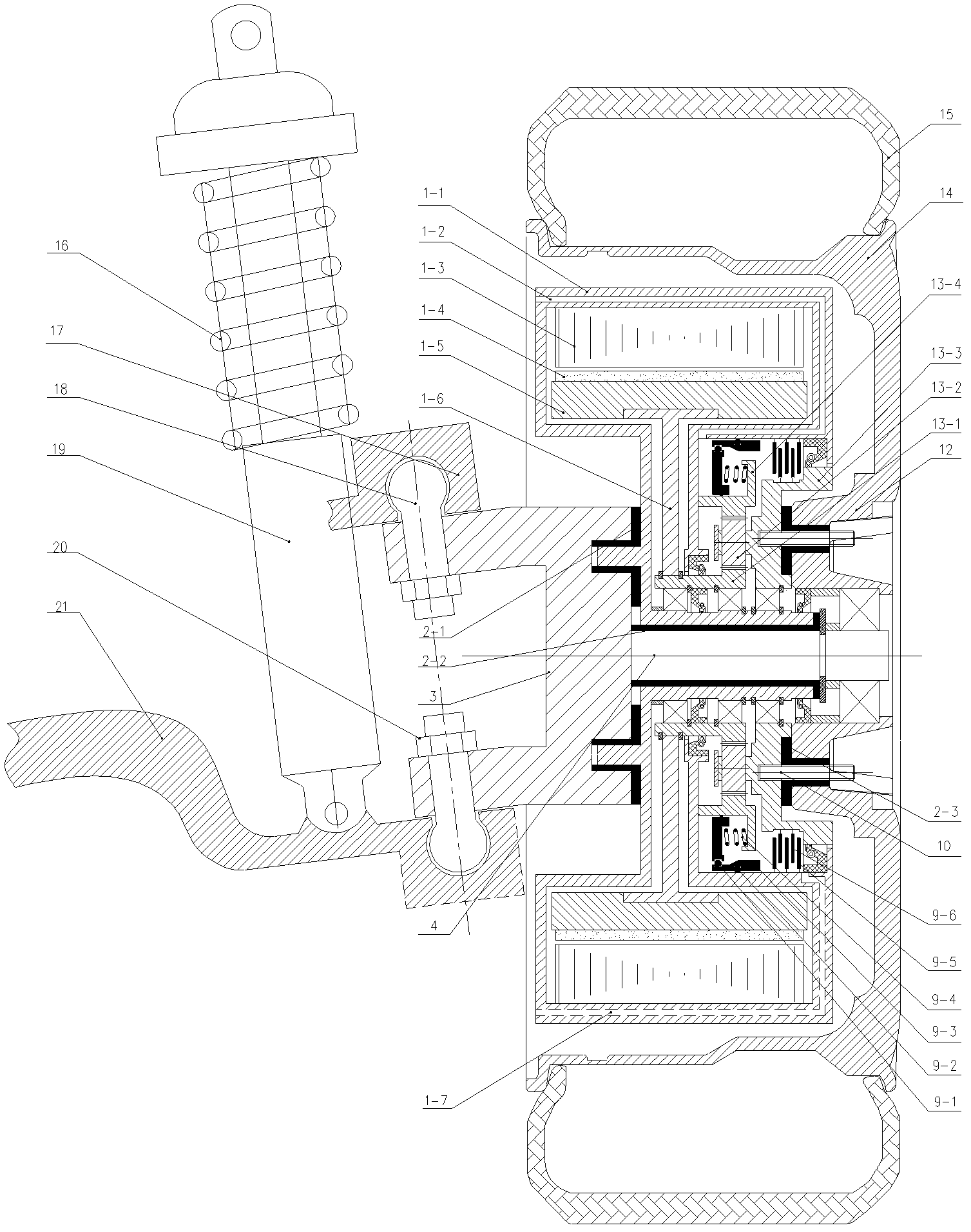
[0037] Such as figure 1 As shown, the built-in suspension integrated hub motor-driven electric wheel of this embodiment includes a hub motor, a brake, a damping mechanism, an unequal-length double wishbone independent suspension and a wheel, and the wheel includes a rim 14, a hub 12, and a tire. 15 and so on.
[0038] The damping mechanism includes an elastic element 2-1 and an elastic element 2-2. The hub motor includes an outer stator (including iron core and windings) 1-3, an inner rotor composed of permanent magnets 1-4 and a rotor yoke 1-5, a housing 1-1, a rotor support frame 1-6, and The stator is fixed on the housing 1-6, the permanent magnets 1-4 are glued to the surface of the rotor yoke 1-5, and the rotor yoke 1-5 is connected to the rotor support frame 1-6 through threads. The housing 1-1 is connected to the joint arm 3 through the first elastic element 2-1, and is connected to the support shaft of the wheel through the elastic element 2-2, which ensures the static o...
Embodiment 2
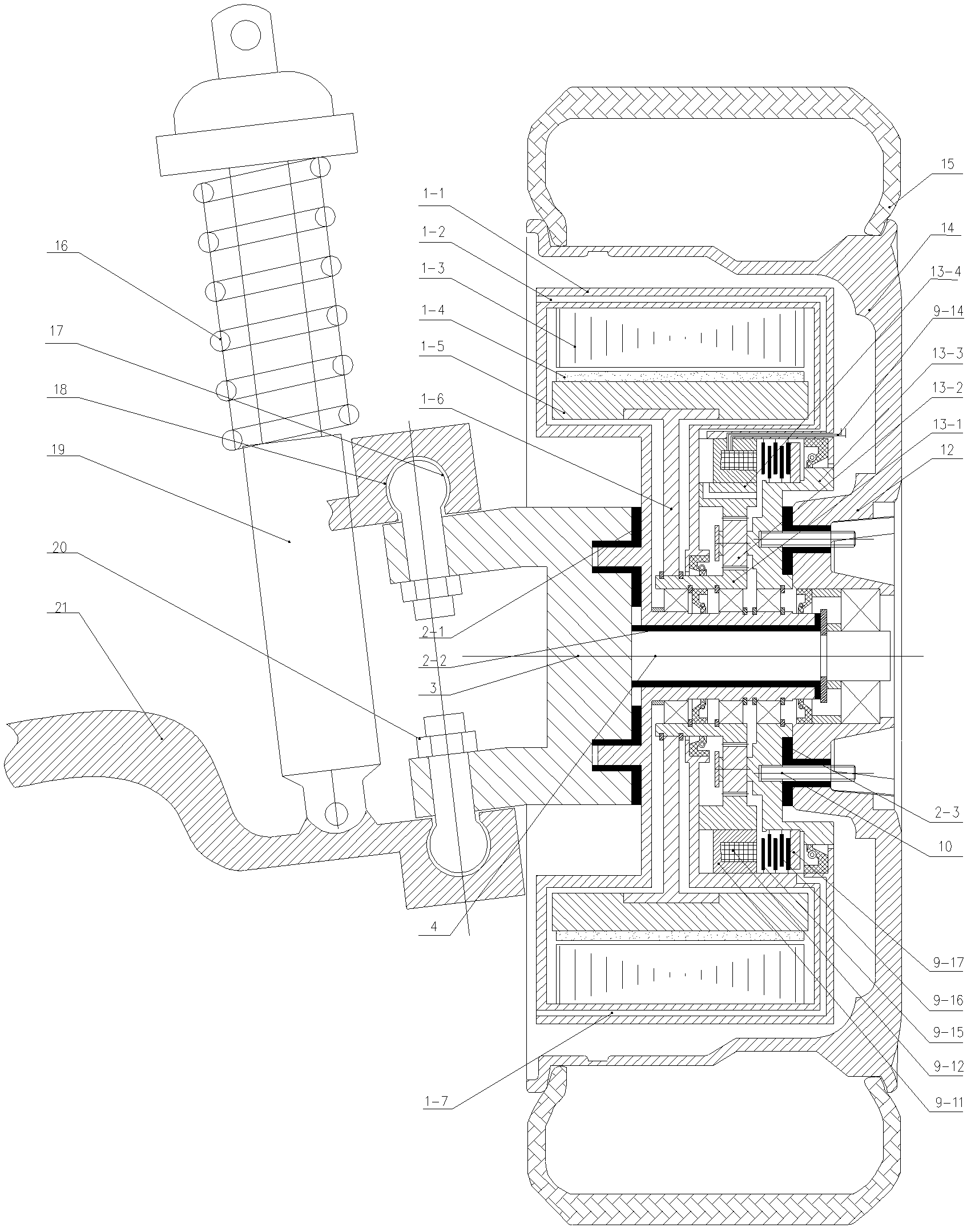
[0045] This embodiment has the same features as the first embodiment except that the brake is an electromagnetic brake disc.
[0046] Such as figure 2 As shown, the brake is a multi-disc electromagnetic brake, including friction plate 9-16, pressure plate 9-15, yoke 9-11, armature 9-17, friction plate 9-16 and armature 9-17 are installed in The planet carrier 13-3 and rotates with the planet carrier 13-2; the pressure plate is installed on the shell 1-1; the coil 9-12 is wound in the inner cavity of the yoke 9-11, and the yoke 9-11 is installed in the In the annular cavity formed by the housing 1-1 and the ring gear 13-4; the lead wires 9-14 of the electromagnetic brake are buried in the surface of the motor housing 1-1. When braking, a current flows in the coil, and the magnetic field in the yoke attracts the armature to the end of the pressure plate, and compresses the pressure plate and the friction plate to achieve braking; when the brake is released, the current in the coil...
Embodiment 3
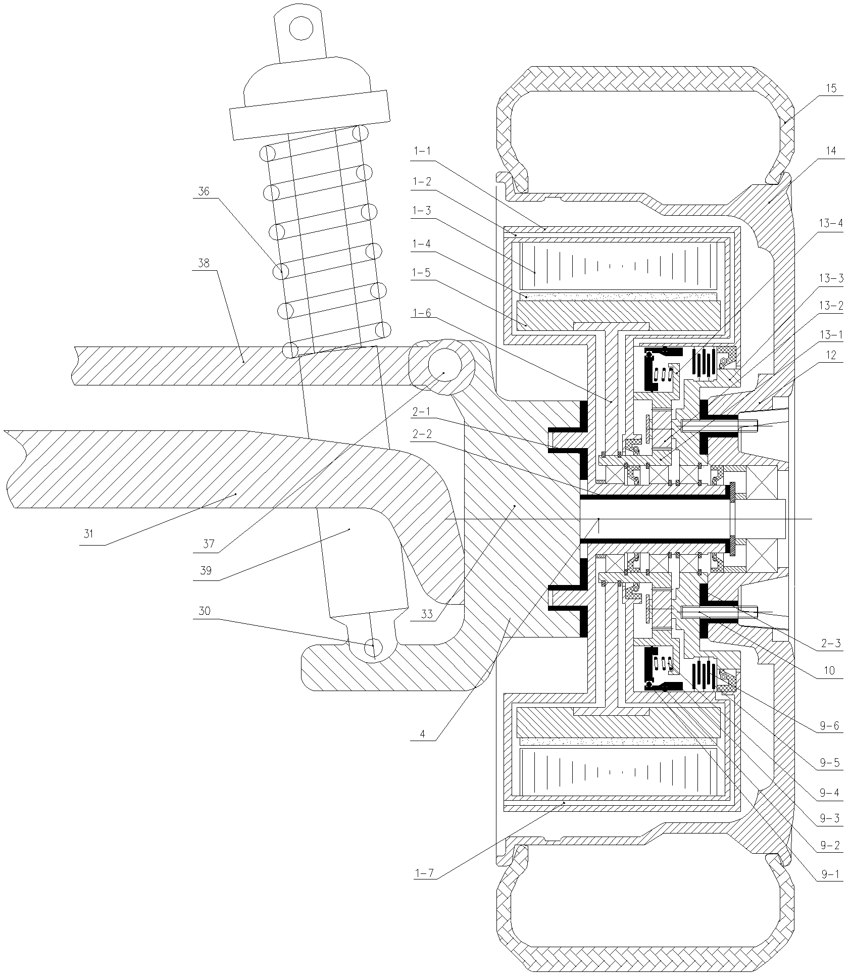
[0049] In this embodiment, except that the unequal-length double wishbone independent suspension is replaced with a multi-link structure, the other features are the same as the first embodiment.
[0050] Such as image 3 As shown, the multi-link structure includes a longitudinal swing arm, a lateral swing arm 31, a transverse tie rod 38, a joint arm 33 and a shock absorber, and the longitudinal swing arm, the lateral swing arm 31 and the joint arm 33 are integrally formed; The longitudinal swing arm and the yaw arm 31 are respectively indirectly connected with the frame through pins; one end of the tie rod 38 is connected with the joint arm through a ball pin 37, and the other end is indirectly connected with the rear cross beam of the frame through a bolt; shock absorber 39 The upper part of the shock absorber is provided with a shock absorber coil spring 36. The upper end of the shock absorber 39 is connected with the body, and the lower end is connected with the joint arm 33 th...
PUM
 Abstract
Description
Claims
Application Information
 - Generate Ideas
- Intellectual Property
- Life Sciences
- Materials
- Tech Scout
- Unparalleled Data Quality
- Higher Quality Content
- 60% Fewer Hallucinations
Browse by: Latest US Patents, China's latest patents, Technical Efficacy Thesaurus, Application Domain, Technology Topic, Popular Technical Reports.
© 2025 PatSnap. All rights reserved.Legal|Privacy policy|Modern Slavery Act Transparency Statement|Sitemap|About US| Contact US: help@patsnap.com


