
Car posture adjusting system of oil-gas suspension

An adjustment system, oil-pneumatic suspension technology, applied in the direction of suspension, elastic suspension, vehicle components, etc., can solve the problem that the stiffness characteristics of elastic components cannot be adjusted, the adjustment method cannot meet the use requirements, and the vehicle's handling performance and ride comfort are reduced, etc. problems, to achieve excellent anti-corrosion and anti-oxidation properties, good mechanical properties, and weight reduction

Active Publication Date: 2012-09-19
CHINA NORTH VEHICLE RES INST
View PDF5 Cites 28 Cited by
  • Summary
  • Abstract
  • Description
  • Claims
  • Application Information

AI Technical Summary

Problems solved by technology

[0002] In the prior art, the stiffness characteristics of the elastic elements of the traditional suspension are not adjustable, and the posture of the vehicle body will change significantly when the vehicle load changes greatly, resulting in a significant decline in the vehicle's handling performance and ride comfort. In this case, foreign companies have realized a two-stage stiffness-adjustable suspension with no-load and full-load through oil-pneumatic springs, but there are not only two states in the actual use of the vehicle, and the uncertainty of the load makes this adjustment method unable to meet the use requirements. , which has also become a technical difficulty faced by domestic vehicle manufacturers and has not been able to effectively solve it, so it is particularly necessary to develop a suspension system with continuously adjustable vehicle posture.

Method used


Image

  • Car posture adjusting system of oil-gas suspension
  • Car posture adjusting system of oil-gas suspension
  • Car posture adjusting system of oil-gas suspension

Examples


Embodiment Construction

[0019] The vehicle posture adjustment system is described in detail below in conjunction with the accompanying drawings:

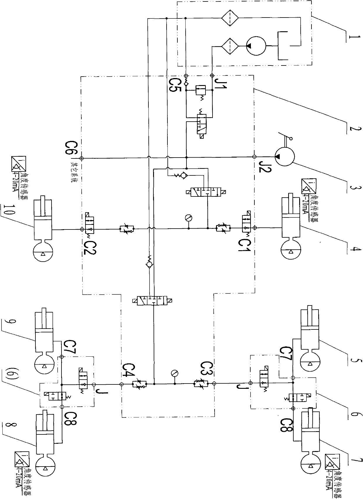
[0020] figure 1 Shown is the schematic diagram of the vehicle posture adjustment system.

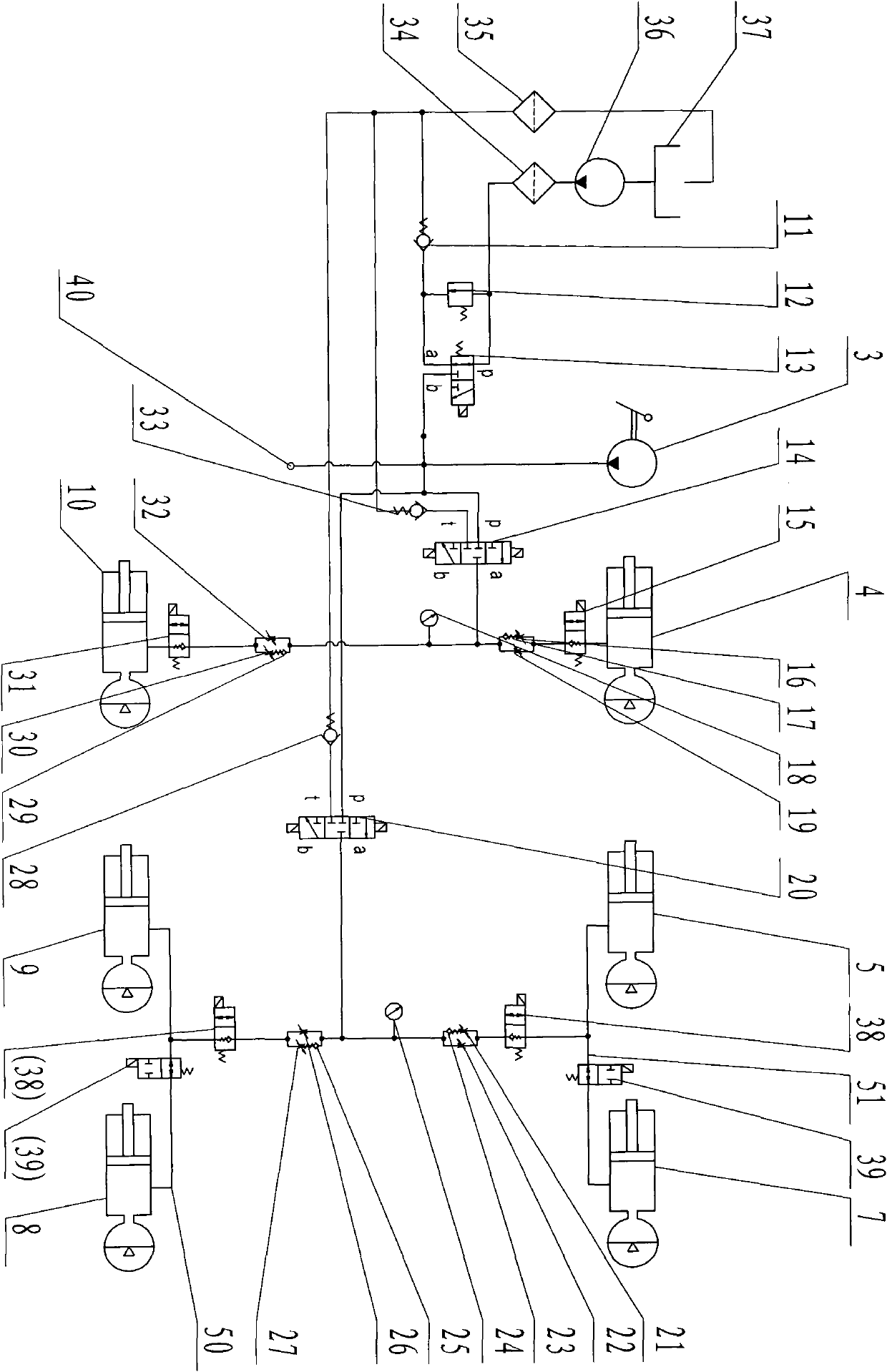
[0021] The vehicle posture adjustment system is composed of a system power source 1, a hydraulic device, a right oil-pneumatic suspension 4, a right two oil-pneumatic suspension 5, a right three oil-pneumatic suspension 7, a left three oil-pneumatic suspension 8, a left two oil-pneumatic suspension 9, The left one oil-gas suspension 10 is composed of electric control device, cables and sensors, and each part is connected by high-pressure hard pipe (or flexible pipe). Preferably, the hydraulic device in the present invention is composed of the suspension device control combination 2 and the communication hydraulic lock combination 6, but those skilled in the art can arbitrarily combine multiple integrated control valves according to actual needs to realize the adjust...


PUM


Abstract

The invention relates to a car posture adjusting system. A power source is connected with an oil tank, an output end of the power source is sequentially in serial connection with an inlet oil filter and an unloading valve, and a two-position three-way solenoid valve can serve as the unloading valve to supply pressure oil to the adjusting system through electromagnetic reversing. An overflow valve is parallelly connected with the unloading valve, and control on critical pressure of the system can be achieved by adjusting a handle. A b end of an oil outlet of the unloading valve is respectively connected with oil inlet ends of a front suspension control valve and a rear suspension control valve through high-pressure hard tubes or hoses, oil outlet ends of the front suspension control valve and the rear suspension control valve are sequentially connected with a throttle valve group and a suspension hydraulic lock serially, and the suspension hydraulic lock is connected with an oil-gas suspension through a pipeline. When the suspension hydraulic lock is powered off, liquid oil in the oil-gas suspension is separated from the car posture adjusting system, so that stability of car postures and driving performance is ensured, and when the suspension hydraulic lock is powered on, the liquid oil in the oil-gas suspension flows back to the oil tank through the car posture adjusting system.

Description

technical field [0001] The invention relates to a vehicle attitude adjustment system using oil and gas springs, belonging to the application fields of hydraulic machinery and motor vehicles. Background technique [0002] In the prior art, the stiffness characteristics of the elastic elements of the traditional suspension are not adjustable, and the posture of the vehicle body will change significantly when the vehicle load changes greatly, resulting in a significant decline in the vehicle's handling performance and ride comfort. In the current situation, foreign companies have realized the suspension form with two stages of adjustable stiffness at full and empty loads through oil and gas springs, but there are not only two states in the actual use of the vehicle, and the uncertainty of the load makes this adjustment method unable to meet the use requirements. , This has also become a technical difficulty that domestic vehicle manufacturers are currently facing and has not be...

Claims


Application Information

Patent Timeline
IPC IPC(8): B60G17/00B60G17/015
Inventor 陈轶杰郑冠慧雷强顺鞠海洁宁丹张亚峰王亚军孟强崔向利韩小玲张旭郭建娟段国柱冯栋梁吕阳
Owner CHINA NORTH VEHICLE RES INST
Learn More