
Universal machine core of rolling mill

A universal rolling mill and core technology, which is applied in the direction of metal rolling mill stand, metal rolling stand, metal rolling, etc., can solve the problems of poor reliability of roll group support, difficult to use effectively, and easy to cause safety accidents. , to achieve the effect of being conducive to popularization and use, improving reliability and maintainability

Inactive Publication Date: 2012-09-19
CISDI ENG CO LTD
View PDF4 Cites 2 Cited by
  • Summary
  • Abstract
  • Description
  • Claims
  • Application Information

AI Technical Summary

Problems solved by technology

However, the structure of the roll group in this way, when the working state is converted to the roll changing state again, because the spring has no active driving force, and the roll group is in the rolling mill frame, people cannot reach it, and the slider cannot be placed in the initial changing position again. The support state of the rolls and the support reliability of the roll group become poor, which is prone to safety accidents, and under harsh working conditions, the operation is inconvenient and the maintainability is poor, making it difficult for this structure to be effectively used at the rolling site

Method used


Image

  • Universal machine core of rolling mill
  • Universal machine core of rolling mill
  • Universal machine core of rolling mill

Examples


Embodiment 1

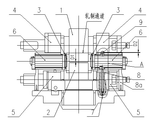
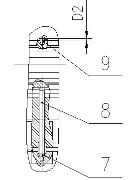
[0024] Such as Figure 1 to Figure 6 As shown, the core of a universal rolling mill includes an upper horizontal roll 1, a lower horizontal roll 2 and a pair of vertical rolls 3 that together form a rolling channel. The two ends of the upper horizontal roll 1 rotate with two upper bearing housings 4 respectively. Cooperate, the two ends of the lower horizontal roll 2 rotate with the two lower bearing housings 5 ​​respectively, and a pair of vertical rolls 3 rotate with the two vertical roll bearing housings 6 respectively. Move out the archway of the rack for roll changing operation. The rolling mill core also includes a quick roll changing device. The quick roll changing device includes a total of four lower horizontal roll positioning rods 7 and four vertical rolls distributed on the left and right sides of the rolling channel. Positioning rods 8, four upper horizontal roll positioning rods 9 and roll changing trolley 10, two positioning rods for lower horizontal rolls and t...

Embodiment 2

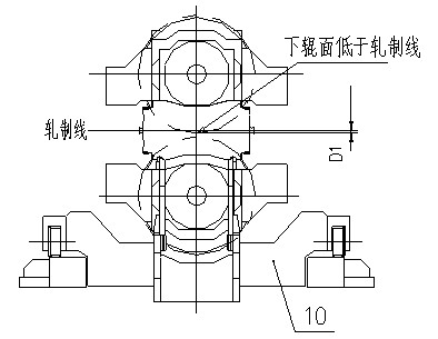
[0033] Such as Figure 7 As shown, the rolling mill core includes an upper horizontal roll 1 and a lower horizontal roll 2, the two ends of the upper horizontal roll 1 are respectively in rotation with the two upper bearing housings 4, and the two ends of the lower horizontal roll 2 are respectively connected with the two lower The bearing seat 5 is rotated and matched, and the movement also includes a quick roll changing device, which includes a total of four lower horizontal roller positioning rods 7, four upper horizontal roller positioning rods 9 and a changing roller located on the left and right sides of the roll gap. Roll trolley 10, two lower horizontal roll positioning rods and two upper horizontal roll positioning rods on each side of the roll gap, respectively distributed in front and back of the lower horizontal roll; The lowest position is supported by the positioning rod 9 of the upper horizontal roll, so that the lower roll surface of the upper horizontal roll i...


PUM


Abstract

The invention discloses a universal machine core of a rolling mill. The universal machine core of the rolling mill comprises an upper horizontal roller and a lower horizontal roller, wherein two ends of the upper horizontal roller are respectively matched with two upper bearing seats in a rotating manner, and two ends of the lower horizontal roller are respectively matched with two lower bearing seats in a rotating manner; and the machine core further comprises a quick roller exchanging device, wherein the quick roller exchanging device comprises a roller exchanging trolley, and is characterized in that: a lower horizontal roller positioning rod and an upper horizontal roller positioning rod are fixed on the roller exchanging trolley, and are distributed at the left side and the right side of a roller gap, counter bores are correspondingly formed on the upper bearing seats respectively, and are used for containing the upper end of the upper horizontal roller positioning rod, depth of the counter bores is D2, when the rolling mill is in a roller exchanging state, the distance from a lower roller surface of the upper horizontal roller to a rolling line is D1, and D2 is smaller than or equal to D1. As the upper horizontal roller is smaller than or equal to the lowest rolling position during the exchange of the rollers, the entire roller group can be reliably supported on the roller exchanging trolley, so that motions of respective rollers in the range of the whole stroke do not interfere with each other when the rolling mill is in operation, and therefore the operation is simple, reliable and safe.

Description

technical field [0001] The invention relates to a universal rolling mill, in particular to a core therein. Background technique [0002] The universal rolling mill core is generally composed of a roll group consisting of a horizontal roll system and a vertical roll system, and a roll changing trolley for supporting the roll group. During the rolling process of the universal rolling mill, the rolls wear out quickly, and the rolls need to be replaced frequently. The roll change process requires: during the roll change operation, the bearing housings of the upper and lower horizontal rolls of the roll group and the bearing housings of the left and right vertical rolls It needs to be supported and placed on the roll changing trolley to form a whole. After the rolls are assembled into the rolling mill, the upper and lower horizontal rolls can freely move up and down within the range of the frame window and the left and right vertical rolls can move freely in the horizontal direct...

Claims


Application Information

Patent Timeline
Patent Type & Authority Applications(China)
IPC IPC(8): B21B31/08B21B13/10
CPCB21B31/103B21B13/10B21B31/08
Inventor 陈义杨虎成李图学李跃林
Owner CISDI ENG CO LTD
Learn More