Intermittent feeding structure of two-stage pusher centrifuge

A two-stage piston and centrifuge technology, applied in the field of centrifuges, can solve problems such as the inability to accurately control the synchronization of feeding and pushing, and achieve the effect of material stability

Active Publication Date: 2012-09-19
ZHEJIANG QINGJI IND
View PDF10 Cites 1 Cited by
  • Summary
  • Abstract
  • Description
  • Claims
  • Application Information

AI Technical Summary

Problems solved by technology

[0003] The purpose of the present invention is to solve the problem of inability to accurately control the synchronization of feeding and pushing through the control of the switch of the feed port to complete the intermittent pushing, and to provide a blocking material with a reasonable structure and synchronized with the first-stage drum. Intermittent feeding structure of two-stage piston pusher centrifuge for intermittent feeding

Method used


Image

  • Intermittent feeding structure of two-stage pusher centrifuge
  • Intermittent feeding structure of two-stage pusher centrifuge
  • Intermittent feeding structure of two-stage pusher centrifuge

Examples


Embodiment Construction

[0020] The technical solutions of the present invention will be further specifically described below through the embodiments and in conjunction with the accompanying drawings.

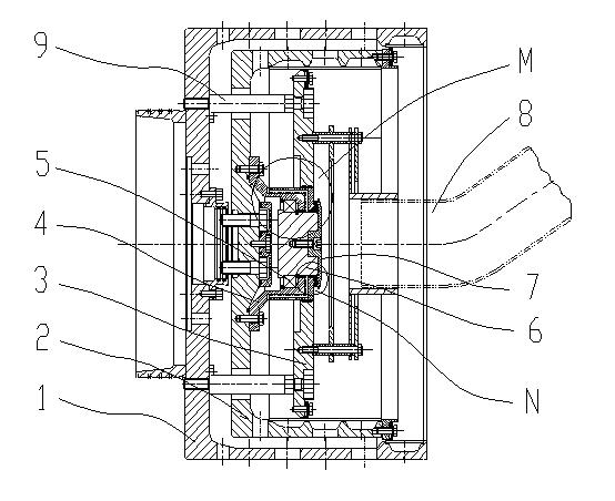
[0021] see figure 1 , the present embodiment is a two-stage piston pusher centrifuge intermittent feeding structure, which is provided with a primary drum 2 and a secondary drum 1, wherein the structure of the secondary drum 1 is connected axially on a circular end plate A tubular body, while the primary drum 2 is completely located in the secondary drum 1, the outer diameter of the tubular body of the primary drum 2 is smaller than the tubular inner diameter of the secondary drum 1, and the length of the tubular body of the primary drum 2 is smaller than that of the secondary drum 1 Drum 1 Length of tubular body.

[0022] Perpendicular to the circular end plate of the secondary drum 1, and set 6 evenly distributed guide shafts 9 along the axial direction in the direction of the tubular body. After th...


PUM


Abstract

The invention relates to the technical field of a centrifuge, in particular to a two-stage feeding structure of a two-stage pusher centrifuge so as to solve the problem that intermittent pushing motion is completed by controlling the switch of a feed port, then the synchronism of feeding and pushing can not be accurately controlled. The structure comprises a secondary drum, feeding pipes and a primary drum arranged in the secondary drum, and is characterized in that a guide shaft is arranged on a round end plate of the secondary drum axially towards a tubular body, passes through a round end plate of the primary drum and is provided with a baffle in the primary drum. A baffle shield is arranged on the round end plate of the primary drum. The external diameter of the baffle shield is in sealing match with through holes at the center of baffle. A rotating shaft is arranged in the baffle shield; a sealing plate is mounted at the end part of the baffle shield; and a protective cover matched with the feeding pipes is arranged on the breadth of the baffle. By an intermittent control system, the material pushing time can be set up. When the material is fed, the material is stable and cannot corrode or abrade the baffle shield and the rear part of the baffle.

Description

technical field [0001] The invention relates to the technical field of centrifuges, in particular to an intermittent feeding structure of a two-stage piston pusher centrifuge. Background technique [0002] The pusher centrifuge is a continuous operation filter centrifuge. Its working principle is to use the high-speed rotation of the drum to generate strong centrifugal force and the filtration and separation of the screen to achieve the purpose of separation and dehydration of the processed solid-liquid mixture. The two-stage pusher centrifuge uses the most common feeding methods for high-level tank natural feeding and screw conveying feeding, as well as intermittent feeding. The usual intermittent feeding is to provide a signal through the pushing material to control the switch of the feeding port to realize intermittent pushing, but this feeding method cannot accurately control the synchronization between feeding and pushing. Such as the patent publication number is CN104...

Claims


Application Information

Patent Timeline
Patent Type & Authority Applications(China)
IPC IPC(8): B04B11/04
Inventor 王刘波
Owner ZHEJIANG QINGJI IND
Why Eureka
Try Eureka