Reverse-osmosis flow timing automatic mechanical flushing valve device

A technology of automatic machinery and flushing valves, applied in reverse osmosis, osmosis/dialysis water/sewage treatment, semi-permeable membrane separation, etc., can solve troublesome and troublesome problems, cannot meet market diversification, increase the cost of electric shock hazards, etc., and achieve The effect of prolonging the service life

Inactive Publication Date: 2012-09-19
ZHEJIANG QINYUAN WATER TREATMENT S T
View PDF6 Cites 0 Cited by
  • Summary
  • Abstract
  • Description
  • Claims
  • Application Information

AI Technical Summary

Problems solved by technology

Manual flushing is cumbersome and troublesome. Many times people will forget or do not flush for a long time. However, the electrical control system needs to add additional circuit control and additio...

Method used


Image

  • Reverse-osmosis flow timing automatic mechanical flushing valve device
  • Reverse-osmosis flow timing automatic mechanical flushing valve device
  • Reverse-osmosis flow timing automatic mechanical flushing valve device

Examples


Embodiment Construction

[0019] Embodiments of the present invention will be described in further detail below in conjunction with the accompanying drawings.

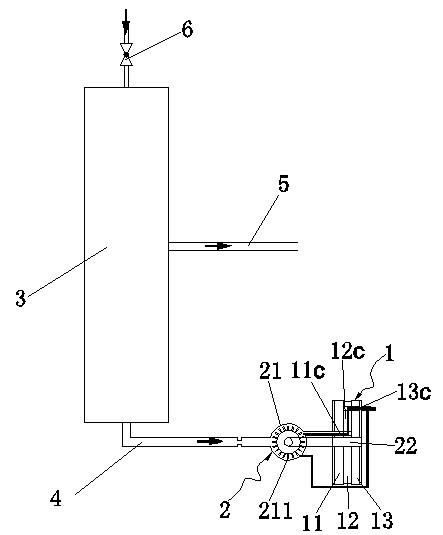
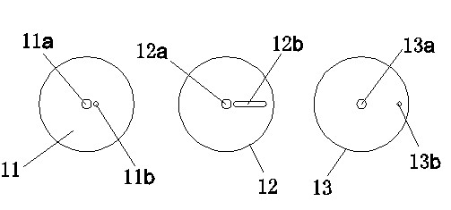
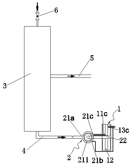
[0020] Figures 1 to 4 Shown is the structural representation of the present invention.

[0021] The reference signs are: mechanical flushing valve 1, first fixed diaphragm 11, first diaphragm shaft hole 11a, first axial through hole 11b, axial flushing water guide hole 11c, movable diaphragm 12, movable diaphragm Shaft hole 12a, radial strip hole 12b, intermediate connecting channel 12c, second fixed diaphragm 13, second diaphragm shaft hole 13a, second axial through hole 13b, axial flushing water channel 13c, energy conversion drive Mechanism 2, energy converter 21, water inlet 21a, first water outlet 21b, second water outlet 21c, impeller 211, conversion output shaft 22, reverse osmosis membrane filter element 3, drain pipe 4, water purification pipe 5, water inlet valve 6.

[0022] like Figure 1 to Figure 4 As shown, a reverse osmosis ...


PUM


Abstract

The invention discloses a reverse-osmosis flow timing automatic mechanical flushing valve device which comprises a mechanical flushing valve. The mechanical flushing valve is connected with an energy conversion driving mechanism, and the energy conversion driving mechanism comprises an energy converter provided with a conversion output shaft, wherein the water inlet end of the energy converter is connected with a water drain pipe opening of a reverse-osmosis membrane filter element, and a first water outlet pipeline of the energy converter is connected with a waste water pool. The tail portion of the conversion output shaft is arranged in a central installing hole of the mechanical flushing valve in a penetrating mode, the mechanical flushing valve is provided with an axial flushing water guide hole connected with a second water outlet of the energy converter, an axial flushing water hole channel and a middle connecting channel, the energy converter converts potential energy produced by flushing water flow discharged by the reverse-osmosis membrane filter element into mechanical energy for driving the conversion output shaft to rotate, and the conversion output shaft drives the middle connecting channel of the mechanical flushing valve to perform rotary movement, thereby achieving periodical communication and non-communication between the axial flushing water guide hole and the axial flushing water hole channel and achieving the purpose of cleaning control through flow timing.

Description

technical field [0001] The invention relates to water purification equipment, in particular to reverse osmosis water purification equipment, in particular to a reverse osmosis flow timing automatic mechanical flushing valve device. Background technique [0002] After long-term use of reverse osmosis water purification equipment, impurities, viruses and other harmful substances in the raw water are intercepted and adsorbed by the filter membrane, which easily leads to blockage of the filter membrane. Clogging of the filter membrane will result in reduced flow or functional failure of the filter membrane. At present, the protection of the filter membrane is mainly through the use of backwashing, and the purpose of purifying the filter membrane is achieved through flushing. In the prior art, reverse osmosis filter membrane flushing is manually controlled flushing or regularly controlled flushing by an electrical control system in two ways. Manual flushing is cumbersome and tr...

Claims


Application Information

Patent Timeline
IPC IPC(8): B01D61/06B01D61/10B01D65/02C02F1/44
Inventor 叶秀友梁建林彭开勤邓鹏
Owner ZHEJIANG QINYUAN WATER TREATMENT S T
Why Eureka
Try Eureka