
A tumor radiotherapy positioning and verification method

A tumor radiotherapy and verification device technology, applied in the field of tumor radiotherapy placement and verification, can solve the problems of reduced placement accuracy, difficult field verification, prolonged placement time, etc., so as to reduce radiation damage, improve field placement and Verify efficiency and avoid occlusion effects

Inactive Publication Date: 2015-10-21
赵 瑞
View PDF2 Cites 0 Cited by
  • Summary
  • Abstract
  • Description
  • Claims
  • Application Information

AI Technical Summary

Problems solved by technology

In order to solve the above problems, the following methods are currently used: (1) For the positioning of the treatment field in a specific treatment situation, use the treatment bed to rotate, use the laser light to align the position, and then turn back to the treatment position for positioning. This method is more troublesome to operate, especially When there are multiple tumors and many radiation fields, the setup time will be significantly prolonged, and the setup accuracy will be affected by the mechanical error of the treatment table.
⑵For the shape verification of multi-leaf collimator, first print out the equal-scale field shape through the treatment planning system, and then directly bond the multi-leaf collimator to the printed paper with the field graphic shape, and observe the shape of the multi-leaf collimator on the paper Through the coincidence of the shadow and the shape of the printed field graphics, the shape of the multi-leaf collimator is verified. This method is not easy to identify the shape of the multi-leaf collimator, and there is a certain difficulty in field verification.

Method used


Image

  • A tumor radiotherapy positioning and verification method

Examples


Embodiment Construction

[0036] The invention relates to a tumor radiotherapy positioning and verification method, which is composed of a radiation field positioning method and a multi-leaf grating shape verification method. in

[0037] The radiotherapy field positioning method includes the following steps:

[0038] ⑴According to the treatment requirements, use the laser positioning lamp to adjust the patient's position at the heavy ion therapy terminal, and mark the cross position of the center of the radiation field on the patient's body surface.

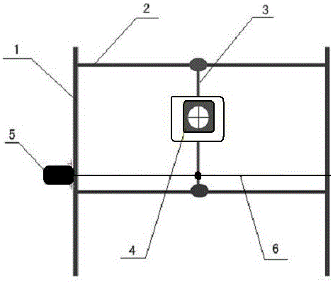
[0039] (2) Use the motor controller in the tumor radiotherapy setup and verification device to control the motor 5 to run to make the tumor radiotherapy setup and the camera 4 in the verification device move from the initial position along the guide rail 2 to the center axis of the treatment field (this position is in the position of the central axis of the treatment field in the tumor radiotherapy It has been determined during installation and debugging...


PUM


Abstract

The invention relates to a positioning and verification method for radiation therapy of tumors. The method consists of a radiation therapy field positioning method and a multileaf collimator shape verification method. The radiation therapy field positioning method comprises the following steps of (1) marking the position of a field center cross on the body surface of a patient; (2) making the center cross of the visual field of a camera in a positioning and verification device for radiation therapy of tumors and the therapy field central axis coincide; (3) showing the shooting field of the camera on a displayer in real time; (4) making the center cross of the visual field and the field center cross on the body surface of the patient coincide; and (5) completing the positioning, and making the camera return to the initial position on a guide rail. The multileaf collimator shape verification method comprises the following steps of: performing the steps of (1) to (4) in the radiation therapy field positioning method; (5) obtaining a corresponding ratio on the optical grating distance of a multileaf collimator; (6) displaying a radiation field shape or virtual multileaf collimator shape of the patient in the visual field of the camera, and making the center of the radiation field shape or virtual multileaf collimator shape of the camera coincide with the center of the visual field of the camera; (7) forming a heavy ion radiation field shape; and (8) completing the multileaf collimator shape verification. The method is simple and convenient.

Description

technical field [0001] The invention relates to the field of radiation therapy, in particular to a method for setting up and verifying tumor radiation therapy. Background technique [0002] In conventional radiotherapy, the laser positioning system is a device used for positioning and positioning of the tumor radiation field. It is composed of a fixed laser lamp that can project a cross and is installed on the obliquely above, left and right of the medical linear accelerator. The operator locates the cross according to the laser cross projection combined with the patient's skin or body membrane, and performs treatment positioning by adjusting the patient's position and the position of the treatment bed where the patient is located. The horizontal treatment terminal of Lanzhou Heavy Ion Accelerator, the experimental equipment for heavy ion clinical treatment carried out in my country, also adopts such a laser positioning system. [0003] The multi-leaf grating is a conformal...

Claims


Application Information

Patent Timeline
Patent Type & Authority Patents(China)
IPC IPC(8): A61N5/10
Inventor 赵瑞魏世华李莎陆军
Owner 赵 瑞
Learn More