Drive control device of alternating-current motor
An AC motor and electric motor technology, which are applied in the direction of AC motor control, motor vibration suppression control, and AC induction motor traction, etc., to achieve the effect of avoiding switching surges
- Summary
- Abstract
- Description
- Claims
- Application Information
AI Technical Summary
Problems solved by technology
Method used
Image
Examples
Embodiment approach 1
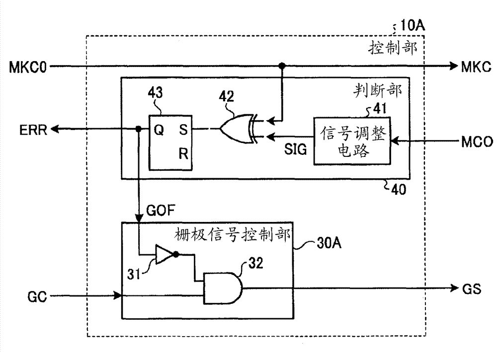
[0033] figure 1 It is a diagram showing a configuration example of the drive control device 100 for an AC motor and related devices connected thereto according to Embodiment 1 or 2 of the present invention. specifically, figure 1 Shown in FIG. 1 is a power collector 1 connected to an overhead line and receiving power, a wheel 3 connected to a rail 2 and driving an electric vehicle, a drive control device 100 for an AC motor, and an AC motor 6 . figure 1 The drive control device 100 of the AC motor shown is configured to include, as a main structure, a power supply open contactor LB as a power supply side switching unit that receives power from the power collector 1 and performs switching of the main circuit on the power supply side. ; The inverter INV converts the DC power received through the positive-side conductor P and the negative-side conductor N into AC power; the capacitor FC has both ends connected to the positive-side conductor P and the negative-side conductor N; t...
Embodiment approach 2
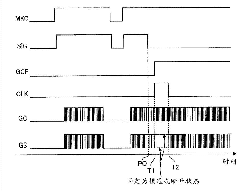
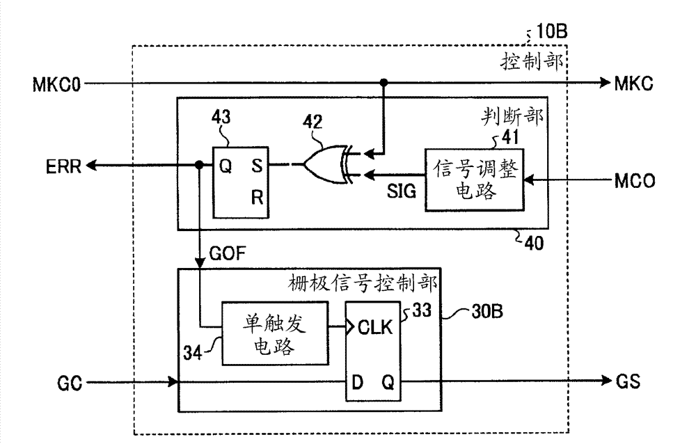
[0062] Figure 13 It is a figure which shows the structural example of the control part 10B in Embodiment 2 of this invention, Figure 14 It is a sequence diagram showing the operation of Embodiment 2 of the present invention. Such as Figure 13 As shown, the structure of the second embodiment differs from that of the first embodiment in the internal structure of the gate signal control unit 30B. Hereinafter, only the parts different from Embodiment 1 will be described.
[0063] First, the configuration of the gate signal control unit 30B will be described. The gate signal control unit 30B is configured to include a one-shot circuit 34 and a D-type flip-flop circuit 33 . The signal GOF output from the judging unit 40 for judging the inconsistency of the operation is input to the one-shot circuit 34, and the output of the one-shot circuit 34 and the basic gate signal GC input from the upper system control unit (not shown) of the control unit 10B are input. To the D-type bi...
Embodiment approach 3
[0069] As in Embodiment 2, when the ON or OFF state of the switching operation is temporarily maintained, a voltage asynchronous to the rotation of the AC motor is applied to the AC motor, and an overcurrent or a torque surge may occur. Therefore, in the third embodiment, the inverter control unit 70 controls the switching state of the inverter INV to be in the zero-voltage vector state (the combination of the switching elements UP, VP, and WP on the upper arm side) during the period from time T1 to T2. All are ON and the UN, VN, WN groups on the lower arm side are all OFF, or the opposite state). In addition, it is preferable to control all switching elements to be turned off after time T2.
[0070] In the case of the above configuration, not only the same effect as that of Embodiment 2 can be obtained, but also since the voltage applied to the AC motor can be made zero between times T1 and T2, it has the advantage of being able to suppress torque surges and overcurrents. Ef...
PUM
 Abstract
Description
Claims
Application Information
 - R&D
- Intellectual Property
- Life Sciences
- Materials
- Tech Scout
- Unparalleled Data Quality
- Higher Quality Content
- 60% Fewer Hallucinations
Browse by: Latest US Patents, China's latest patents, Technical Efficacy Thesaurus, Application Domain, Technology Topic, Popular Technical Reports.
© 2025 PatSnap. All rights reserved.Legal|Privacy policy|Modern Slavery Act Transparency Statement|Sitemap|About US| Contact US: help@patsnap.com


