
High/low-speed groove clutch friction plate

A technology of clutches and friction plates, which is applied in the field of vehicle gearboxes, can solve the problems of increased belt displacement torque and power loss, large belt displacement torque, and increased temperature rise of lubricating oil, etc., to reduce belt displacement torque and power loss , Increase the oil damping, reduce the effect of the belt displacement torque

Inactive Publication Date: 2012-09-12
BEIJING INSTITUTE OF TECHNOLOGYGY
View PDF6 Cites 5 Cited by
  • Summary
  • Abstract
  • Description
  • Claims
  • Application Information

AI Technical Summary

Problems solved by technology

With the increase of engine speed and gearbox power density of heavy-duty vehicles, the speed difference between the friction plate and the separation steel plate of the wet clutch increases, resulting in greater belt-disc torque and power loss, which affects the efficiency of the transmission system ; Long-term operation is more likely to increase the temperature rise of the lubricating oil, and the lubricating oil will decompose and deteriorate
Tests have proved that due to the free gap between the clutch friction plate and the separation plate, with the further increase of the speed difference, the friction plate and the separation plate will vibrate violently, causing mutual collision friction, resulting in belt row torque and power loss The sharp rise of the oil will seriously affect the transmission efficiency and the life of the lubricating oil, and even cause the vibration and noise inside the gearbox

Method used


Image

  • High/low-speed groove clutch friction plate
  • High/low-speed groove clutch friction plate
  • High/low-speed groove clutch friction plate

Examples


Embodiment Construction

[0016] The specific implementation of the present invention will be further described below in conjunction with the accompanying drawings and examples. The following examples are only used to illustrate the technical solutions of the present invention more clearly, but not to limit the protection scope of the present invention.

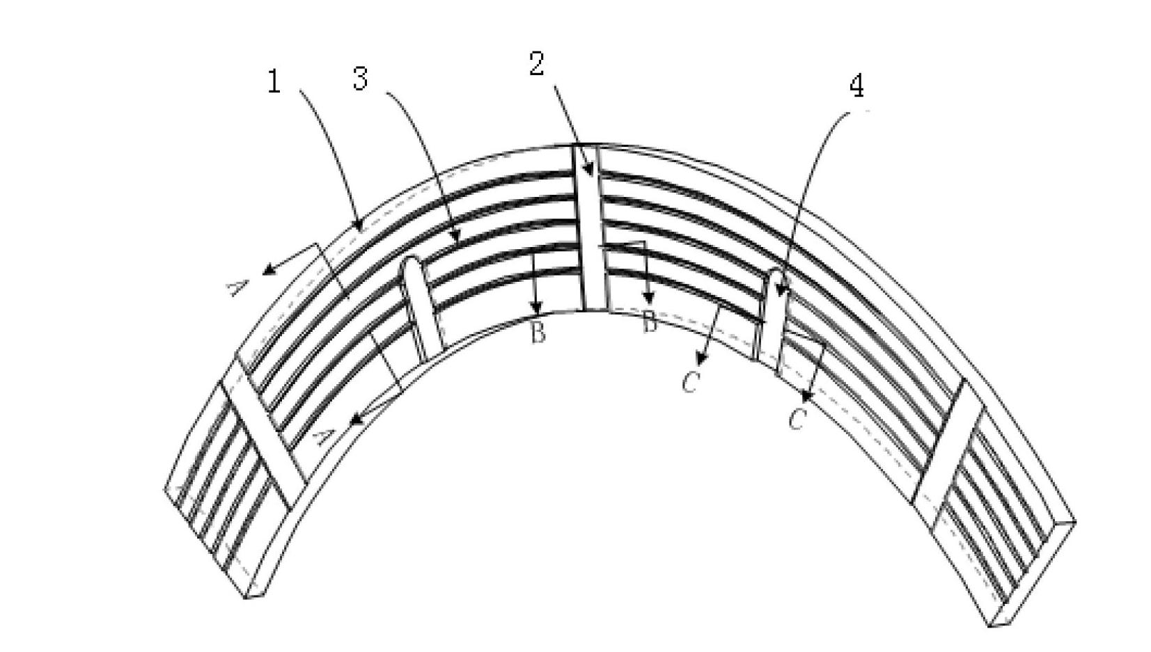
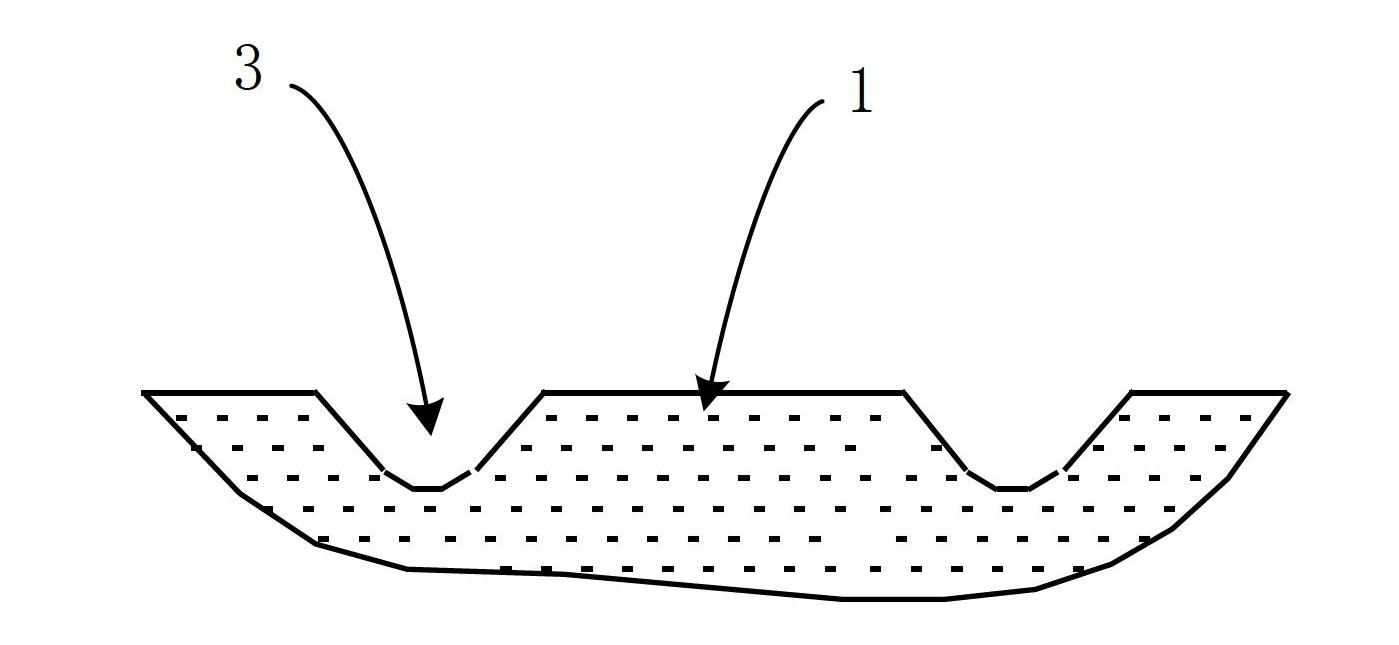
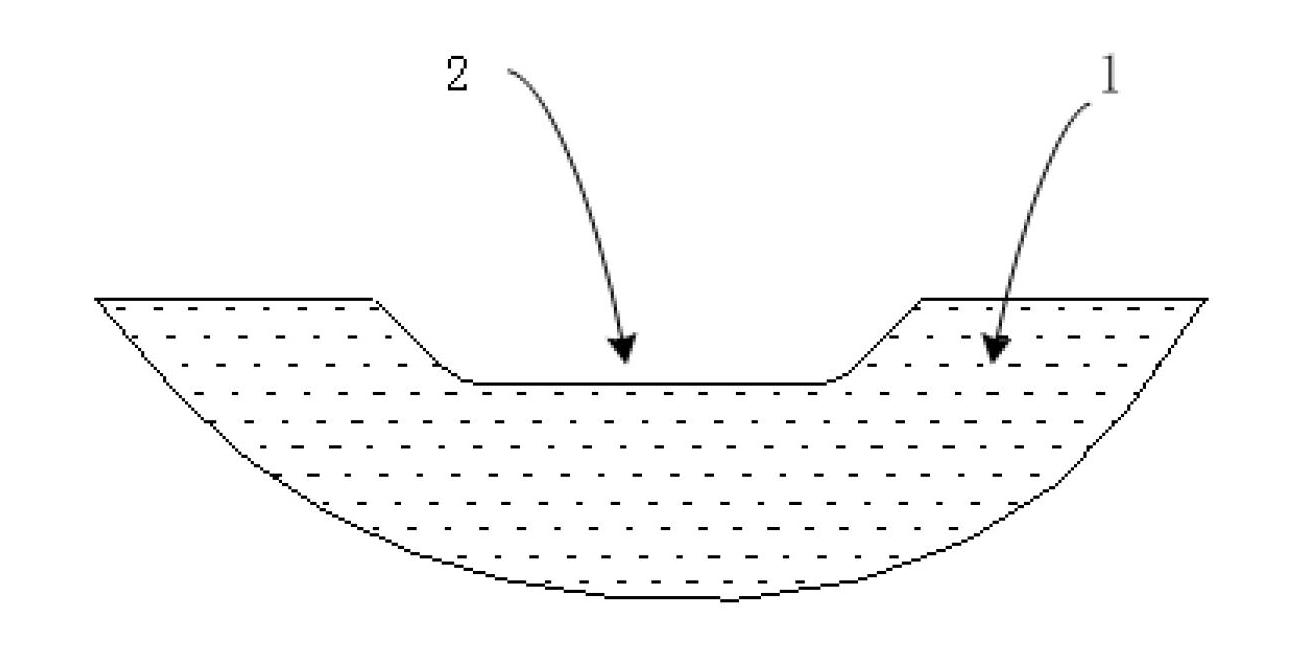
[0017] Such as Figure 1 to Figure 4 As shown, the technical solution for the specific implementation of the present invention is: a high-low speed groove clutch friction plate, on which the circular surface of the clutch friction plate 1 is provided with spiral grooves 3 at equal intervals along the circumferential direction, and along the radial direction of the clutch friction plate 1, etc. There are through grooves 2 and half through grooves 4 at intervals, the through grooves 2 and half through grooves 4 are arranged at intervals, and the through grooves 2 and half through grooves 4 are connected with the spiral groove 3 .

[0018] The cross-sect...


PUM


Abstract

The invention belongs to the technical field of vehicle gearboxes and relates to a clutch friction plate, in particular to a high / low-speed groove clutch friction plate. Spiral grooves are formed on a circular ring surface of the clutch friction plate along the circumferential direction in equal distance; through grooves are formed along the radial direction of the clutch friction plate in equal distance; semi-through grooves are formed along the radial direction of the clutch friction plate in equal distance; and the through grooves and the semi-through grooves are formed at intervals and are communicated with the spiral grooves. In the joint process, the clutch friction plate has a lubricating function, large-area dry friction of the friction plate is avoided, and wear of the friction plate is reduced; and during an empty load, radial flow of oil is accelerated, and the probability of forming a complete oil film is reduced, so that the clutch friction plate has the advantage of reducing the drag torque at low speed.

Description

technical field [0001] The invention belongs to the technical field of vehicle gearboxes, and relates to a clutch friction plate, in particular to a high-low speed groove clutch friction plate. Background technique [0002] In the prior art, a wet clutch is a device widely used in heavy-duty vehicle gearboxes to transmit and cut off torque. In order to increase the transmitted torque, it is usually composed of multiple plates. With the increase of engine speed and gearbox power density of heavy-duty vehicles, the speed difference between the friction plate and the separation steel plate of the wet clutch increases, resulting in greater belt-disc torque and power loss, which affects the efficiency of the transmission system ; Long-term operation is more likely to increase the temperature rise of the lubricating oil, and the lubricating oil will decompose and deteriorate. Tests have proved that due to the free gap between the clutch friction plate and the separation plate, wi...

Claims


Application Information

Patent Timeline
Patent Type & Authority Applications(China)
IPC IPC(8): F16D13/64
Inventor 胡纪滨彭增雄苑士华李雪原荆崇波魏超林硕
Owner BEIJING INSTITUTE OF TECHNOLOGYGY
Learn More