System and method for dense-stochastic-sampling imaging

An imaging system and subsystem technology, applied in image data processing, image data processing, material excitation analysis, etc., can solve problems that cannot be used to obtain

Active Publication Date: 2012-09-05
莱卡微系统 CMS +1
View PDF4 Cites 5 Cited by
  • Summary
  • Abstract
  • Description
  • Claims
  • Application Information

AI Technical Summary

Problems solved by technology

Scanning tunneling and atomic force microscopy are non-optical techniques used to obtain high-resolution images of material surfaces, but cannot be used to obtain information about the nanoscale or microscale content of the sample volume below the surface
All types of microscopy are bound by resolution limitations in one way or another, but optical microscopy is associated with the perhaps famous resolution limitation known as the "diffraction limit", which divides conventional visible light Optical microscopy is limited to a resolution limit of approximately 200 nm

Method used


Image

  • System and method for dense-stochastic-sampling imaging
  • System and method for dense-stochastic-sampling imaging
  • System and method for dense-stochastic-sampling imaging

Examples


Embodiment Construction

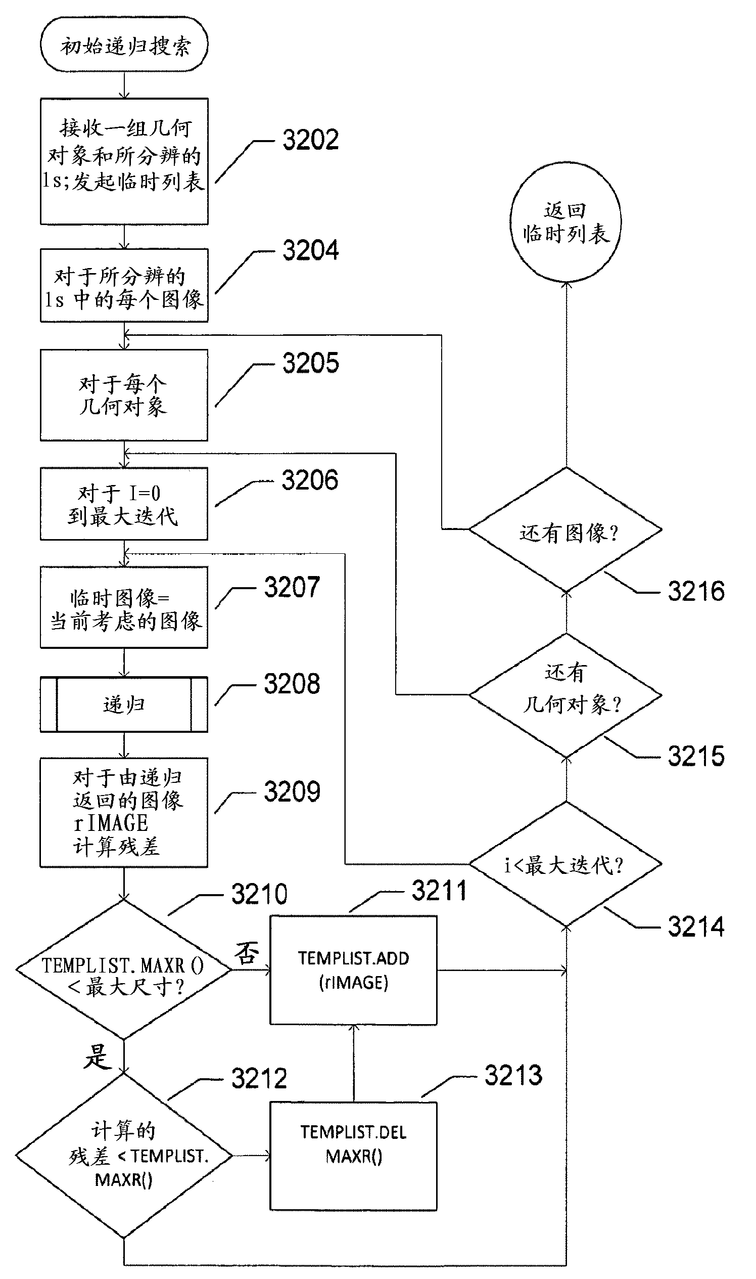
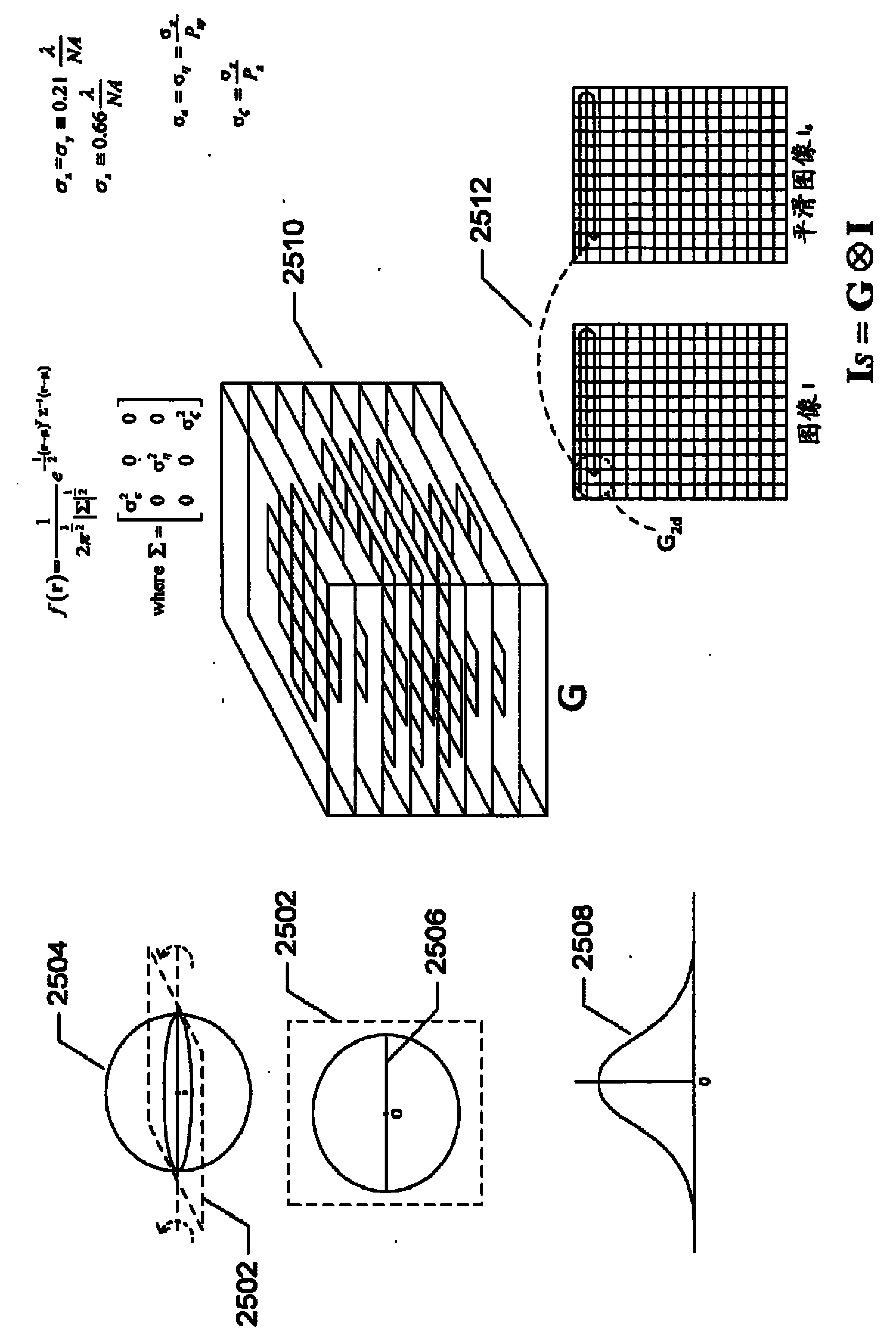
[0029] Embodiments of the present invention relate to imaging techniques, and in particular, to imaging systems that detect relatively weak signals over time and use the detected signals to determine the location of signal emitters. In the following discussion, embodiments of the present invention are used as a context for describing the present invention, wherein embodiments of the present invention relate to imaging of samples, in particular biological samples, at a resolution greater than the so-called diffraction-limited resolution of a conventional optical microscope. Methods and Instruments. However, alternative embodiments of the present invention relate to many other imaging applications. As discussed in more detail below, embodiments of the present invention employ various computational imaging processing methodologies for disambiguating overlapping emitter images, for hierarchically fitting geometric cells to images to further refine original images, and Used to int...


PUM


Abstract

Embodiments of the present invention are directed to imaging technologies, and, in particular, to an imaging system that detects relatively weak signals, over time, and that uses the detected signals to determine the positions of signal emitters. Particular embodiments of the present invention are directed to methods and systems for imaging fluorophore-labeled samples in order to produce images of the sample at resolutions significantly greater than the diffraction-limited resolution associated with optical microscopy. Embodiments of the present invention employ overlapping-emitter-image disambiguation to allow data to be collected from densely arranged emitters, which significantly decreases the data-collection time for producing intermediate images as well as the number of intermediate images needed to computationally construct high-resolution final images.; Additional embodiments of the present invention employ hierarchical image-processing techniques to further resolve and interpret disambiguated images.

Description

[0001] Cross References to Related Applications [0002] This application claims the benefit of Provisional Application No. 61 / 289,916, filed December 23, 2009. technical field [0003] The present invention relates to imaging techniques, and in particular, to imaging systems that detect relatively weak signals over time and use the detected signals to determine the location of signal emitters. Background technique [0004] Many different types of imaging systems are used in modern scientific research to acquire images of small or distant objects, including very high-resolution electron microscopes, very high-resolution scanning tunneling (STM) and atomic force (AFM) imaging instruments, and many Different types of optical microscopes, telescopes and image generating sensors. As with most types of imaging devices, instruments, and techniques, there are many different tradeoffs and balances associated with different types of microscopy. For example, transmission electron mi...

Claims


Application Information

Patent Timeline
Patent Type & Authority Applications(China)
IPC IPC(8): G01N21/64G06T1/00
Inventor G.达努瑟P.C.古德文
Owner 莱卡微系统 CMS
Why Eureka
Try Eureka