Multiple-part inner housing for a steam turbine

A technology of inner shell and shell, which is applied in the direction of engine components, mechanical equipment, machines/engines, etc., can solve the problems of low tonnage and castability, heavy inner shell parts, expensive nickel-based materials, etc., and achieve cost savings , expand the supplier system, expand the effect of production capacity

Inactive Publication Date: 2012-09-05
SIEMENS AG
View PDF12 Cites 0 Cited by
  • Summary
  • Abstract
  • Description
  • Claims
  • Application Information

AI Technical Summary

Problems solved by technology

Nickel-based materials used in such turbines are relatively expensive
Furthermore, manufacturing is limited to low tonnage and castability
Furthermore, the inner housing parts made of a single piece are relatively heavy and large

Method used


Image

  • Multiple-part inner housing for a steam turbine
  • Multiple-part inner housing for a steam turbine
  • Multiple-part inner housing for a steam turbine

Examples


Embodiment Construction

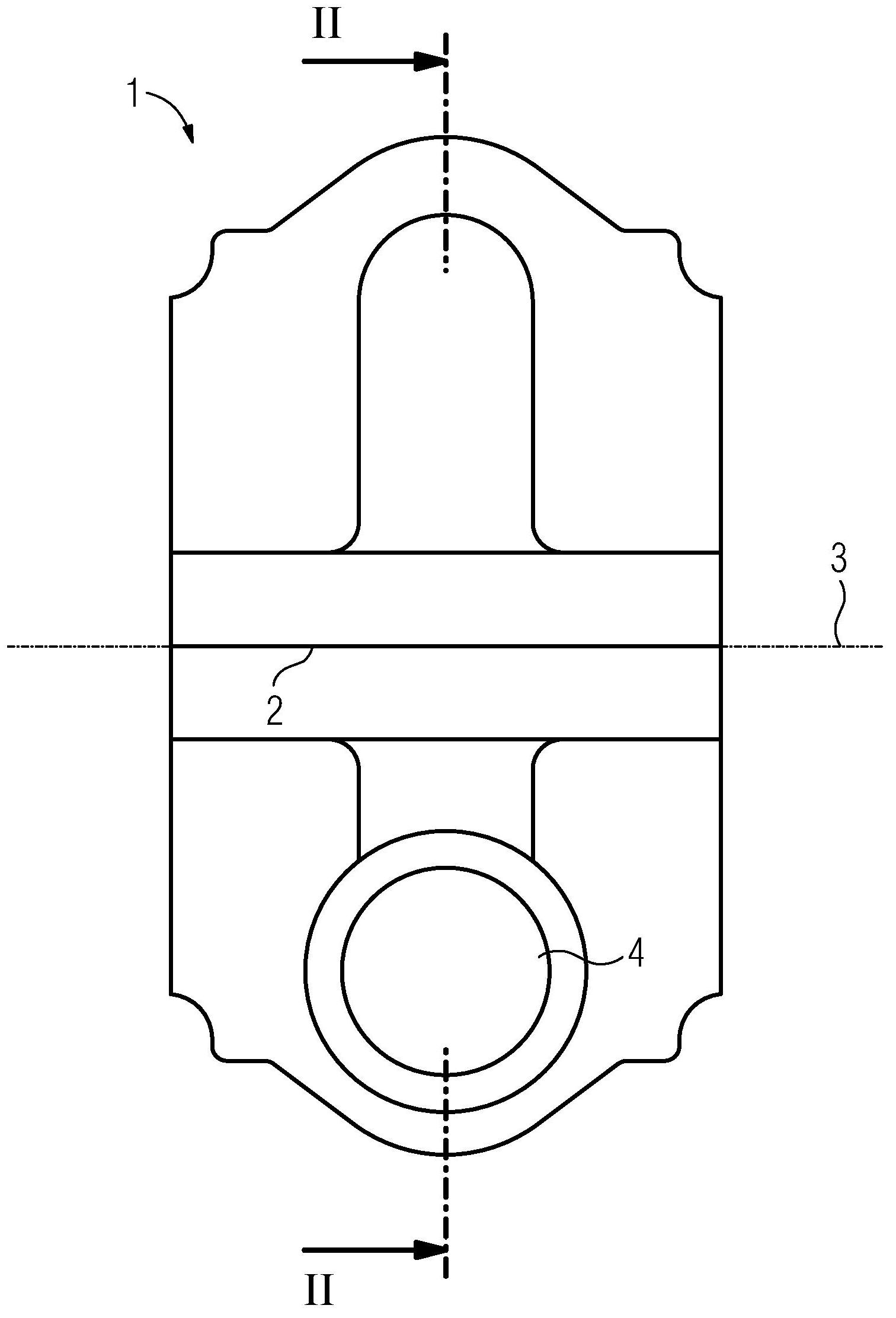
[0026] figure 1 A side view of the inner housing 1 of the fluid machine is shown. Such a fluid machine can be, for example, a steam turbine or a gas turbine. The following embodiments relate to steam turbines. The inner housing 1 includes a horizontal joint surface 2 and is substantially symmetrical about an axis of rotation 3 . A rotor, not shown in detail, is mounted rotatably about an axis of rotation 3 within the inner housing 1 .

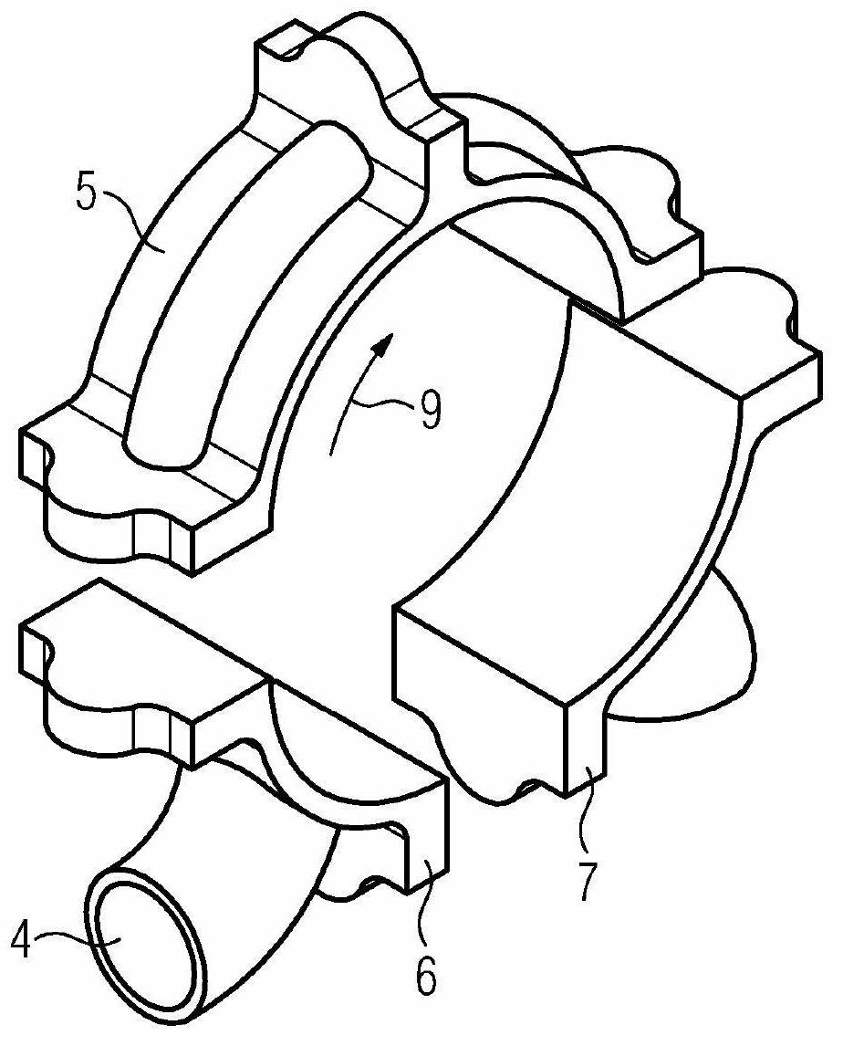
[0027] The upper inner housing parts 5 , 10 , 11 are formed above the horizontal joint surface 3 and the lower inner housing parts 6 , 7 are formed below the horizontal joint plane 2 . The lower inner housing parts 6 , 7 below the horizontal joint surface 2 essentially have the inflow connection 4 . figure 1 Both an inner housing consisting of three inner housing parts and an inner housing consisting of four inner housing parts are shown.

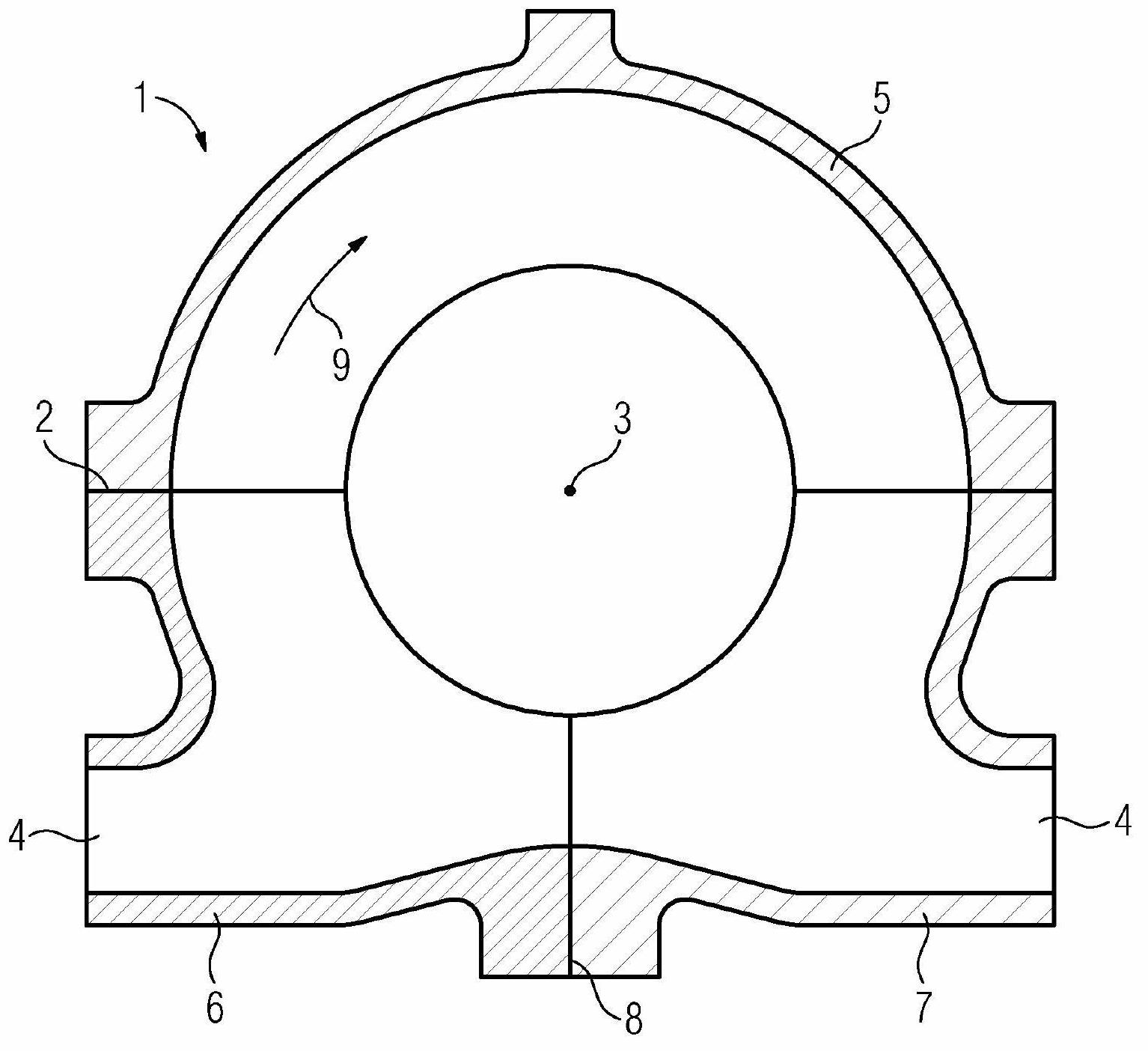
[0028] figure 2 show figure 1 The section along the line A of the inner housing 1 in . The inner...


PUM


Abstract

The invention relates to an inner housing (1) for a flow machine, wherein the inner housing (1) is formed at least from three inner-housing parts as viewed in the circumferential direction.

Description

technical field [0001] The invention relates to an inner housing for a turbomachine and a method for producing the inner housing for a turbomachine. Background technique [0002] A fluid machine is understood to mean, for example, a steam turbine. Typically, a steam turbine has a rotatably mounted rotor and a housing disposed around the rotor. A flow channel is formed between the rotor and the inner housing. Housings in steam turbines must be able to fulfill multiple functions. Firstly, the guide vanes in the flow channels are arranged on the housing, and secondly, the inner housing must withstand the pressure and temperature of the fluid medium for all load cases and special operating conditions. In a steam turbine, the fluid medium is steam. Furthermore, the housing must be designed in such a way that the introduction and removal of what is also referred to as drainage is possible. Another function that must be fulfilled by the housing is the possibility of threading ...

Claims


Application Information

Patent Timeline
Patent Type & Authority Applications(China)
IPC IPC(8): F01D25/26F01D25/24F01D25/14F01D25/28
CPCF01D25/265F01D25/14F01D25/24F01D25/243F01D25/26F01D25/28F05C2201/0466F05D2220/31F05D2220/72F05D2240/14
Inventor 汉斯·克拉森本亚明·克洛斯-格罗特亨宁·阿尔姆斯泰特
Owner SIEMENS AG
Why Eureka
Try Eureka