Ink box and body structure of ink box possessing multiple compartments
A technology of ink cartridges and inks, which is applied in printing and other directions, and can solve problems such as ink mixing
- Summary
- Abstract
- Description
- Claims
- Application Information
AI Technical Summary
Problems solved by technology
Method used
Image

Examples
no. 1 example
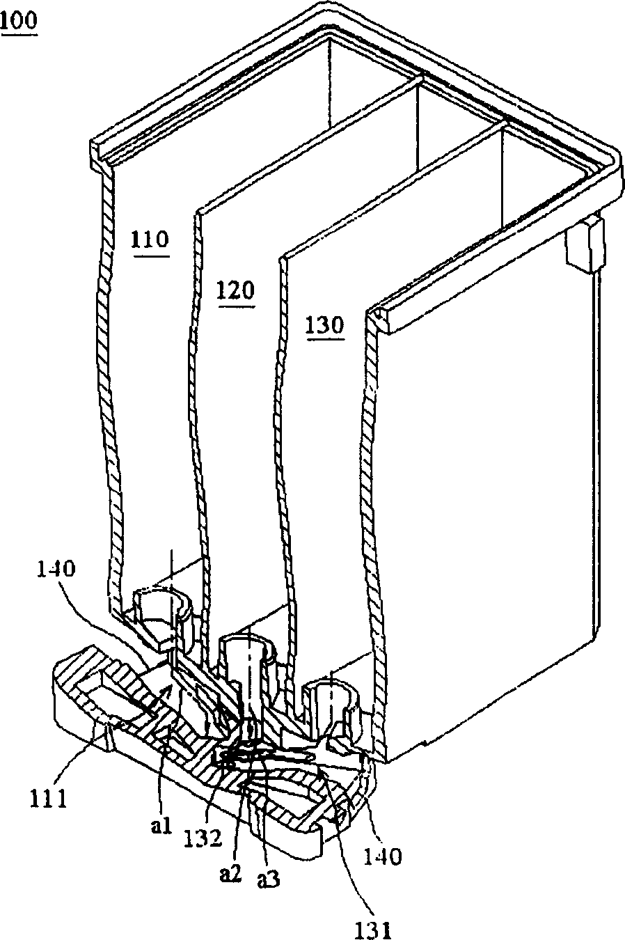
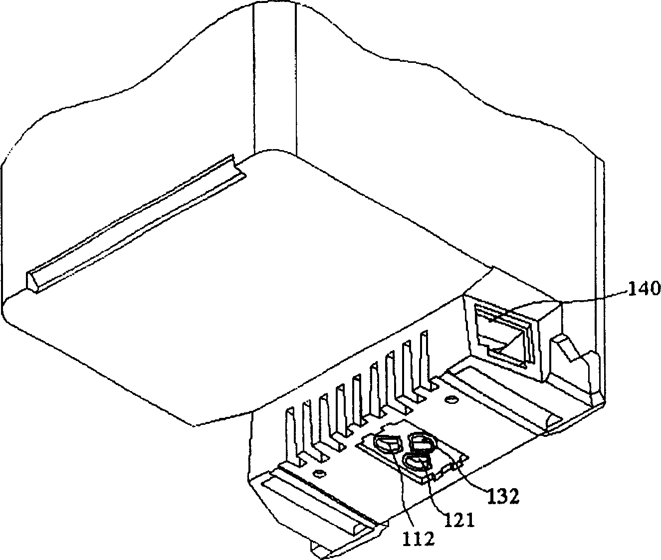
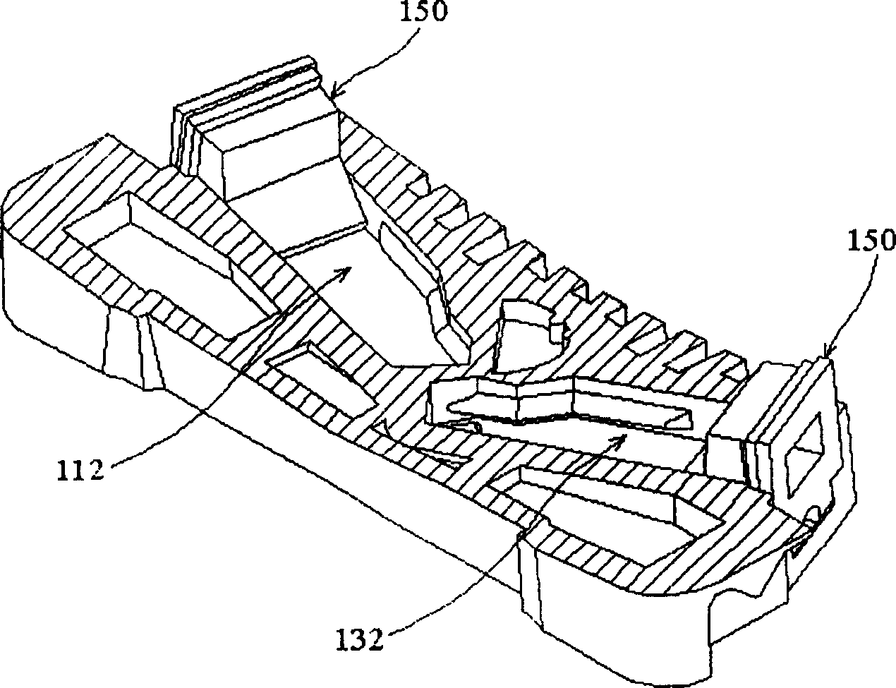
[0036] Figure 3a , 3b , 3c, 3d show the ink cartridge 300 of the first embodiment of the present invention, which can be used to eject ink I, and includes a body 310, a sealing member 320, an inkjet driver chip 330, and an outer cover 340, wherein The body 310 and the sealing member 320 constitute the body structure 700 of the ink cartridge of this embodiment.
[0037]The main body 310 is a container shape, by means of its outer wall, the ink I is contained in the main body 310, and by means of its inner wall, the inside of the main body 310 is divided into a first chamber 311, a second chamber 312, and a third chamber 313, wherein the first chamber 311, the second chamber 312, and the third chamber 313 are respectively used to accommodate inks of different colors, and the first chamber 311 and the third chamber 313 are respectively located at the sides of the second chamber 312 Both sides, ie, the first chamber 311 , the second chamber 312 , and the third chamber 313 are f...
no. 2 example
[0053] Figure 4 The ink cartridge 400 of the second embodiment of the present invention is shown, which includes a body 410, a sealing member 420, and an inkjet driver chip 430. It should be understood that in this embodiment, the comparison with the first embodiment is omitted. Example of the description of the same structure, for example, the outer cover and the like.
[0054] The body 410 divides the interior of the body 410 into a first chamber 411, a second chamber 412, and a third chamber 413 by means of inner walls, wherein the first chamber 411 and the third chamber 413 are respectively located in the second chamber 412 The two sides, that is, the first chamber 411, the second chamber 412, and the third chamber 413 are formed in the body 410 in a juxtaposed manner; it should be noted that in this embodiment, the second chamber 412 and The partition 419b between the third chambers 413 is an inclined plane, such as Figure 4 As shown, that is, the partition 419b separ...
no. 3 example
[0064] Figure 5 The ink cartridge 500 of the third embodiment of the present invention is shown, which includes a body 510, a sealing member 520, and an inkjet driver chip 530. It should be understood that in this embodiment, the comparison with the first embodiment is omitted. Example of the description of the same structure, for example, the outer cover and the like.
[0065] The body 510 divides the interior of the body 510 into a first chamber 511, a second chamber 512, and a third chamber 513 by means of an inner wall, wherein the second chamber 512 and the third chamber 513 are formed in the body in a parallel manner 510, while the second chamber 512 and the third chamber 513 are located on the same side of the first chamber 511, that is, the chambers 511, 512, 513 are arranged adjacent to each other, and are arranged in a row and in two rows Arrangement.
[0066] Furthermore, the body 510 also has a first outlet 514 , a second outlet 515 , and a third outlet 516 at i...
PUM
 Abstract
Description
Claims
Application Information
 - R&D
- Intellectual Property
- Life Sciences
- Materials
- Tech Scout
- Unparalleled Data Quality
- Higher Quality Content
- 60% Fewer Hallucinations
Browse by: Latest US Patents, China's latest patents, Technical Efficacy Thesaurus, Application Domain, Technology Topic, Popular Technical Reports.
© 2025 PatSnap. All rights reserved.Legal|Privacy policy|Modern Slavery Act Transparency Statement|Sitemap|About US| Contact US: help@patsnap.com