Lens packaging device

A lens and clamping technology, applied in packaging and other directions, can solve problems such as lens surface damage, achieve the effects of reducing labor costs, improving product yield, and improving production efficiency

Pending Publication Date: 2020-04-17
东莞旭和光电科技有限公司
View PDF0 Cites 0 Cited by
  • Summary
  • Abstract
  • Description
  • Claims
  • Application Information

AI Technical Summary

Problems solved by technology

[0004] The purpose of the present invention is to provide a lens packaging device to solve the problem of effectively ensuring the damage of the lens surface caused by finger contact with the lens in the existing method

Method used


Image

  • Lens packaging device
  • Lens packaging device
  • Lens packaging device

Examples


Embodiment 1

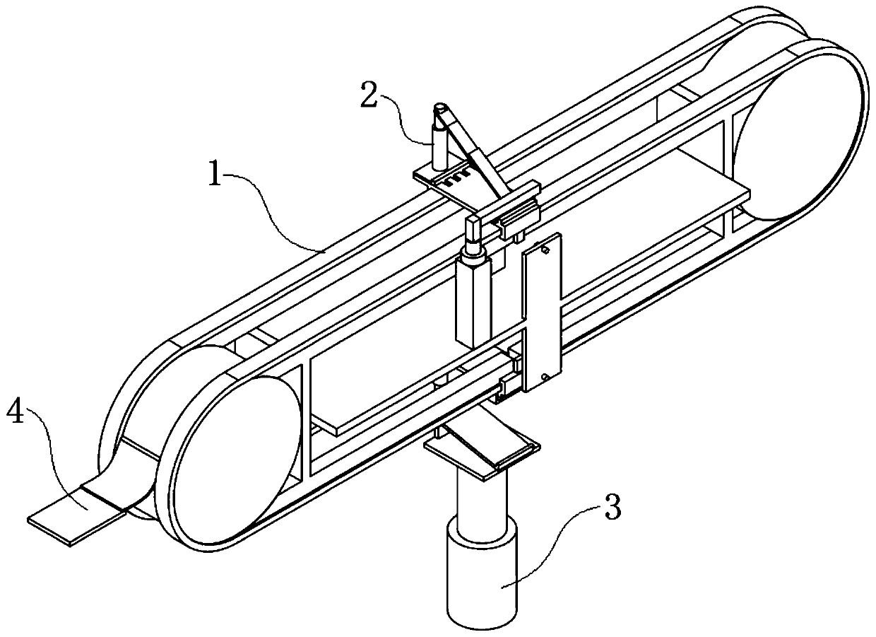
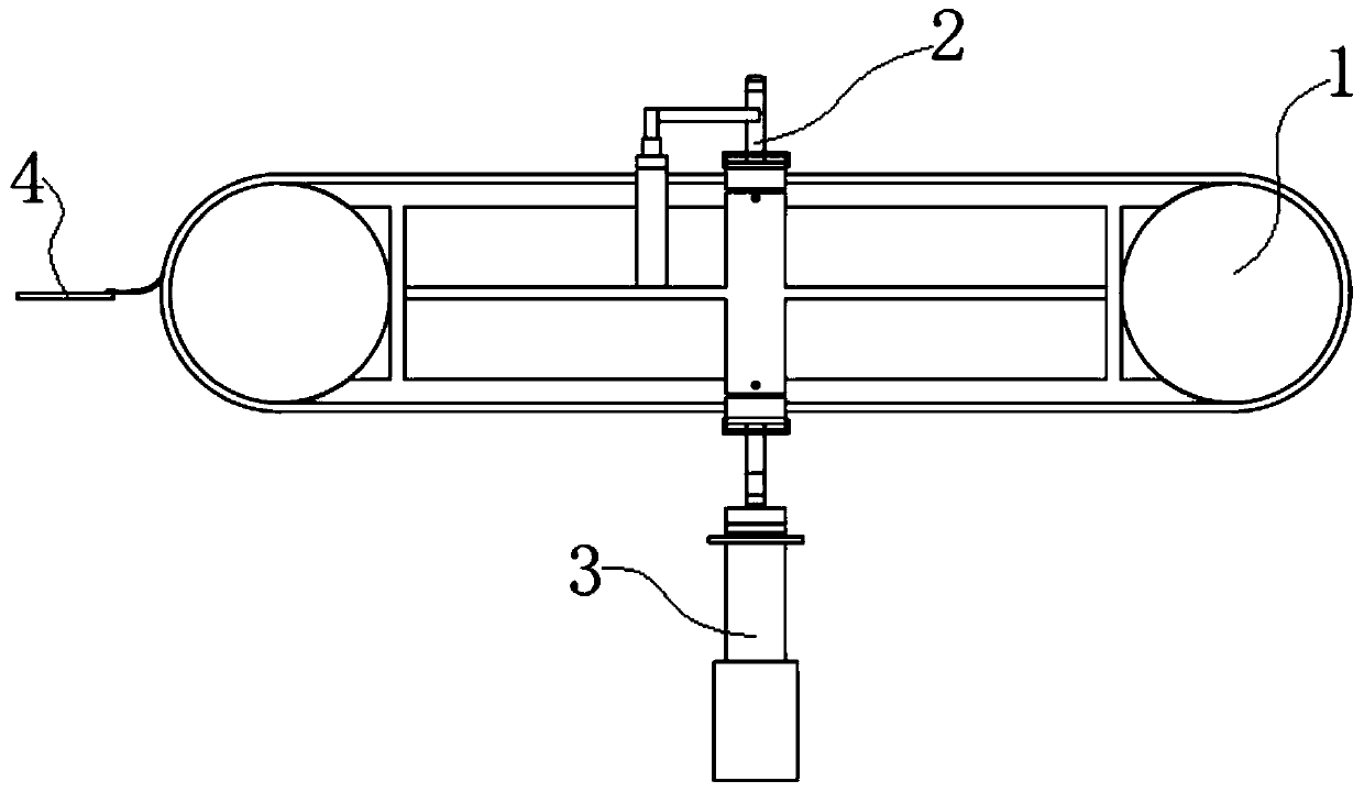
[0033] see Figure 1-2 As shown, the present invention is a lens packaging device, including a rotating frame 1, a clamping seat 2, a loading arm 3 and a material guide plate 4, a number of clamping seats 2 are connected and matched with the rotating frame 1, and the loading arm 3 is connected to the clamping The seats 2 cooperate with each other, the material guide plate 4 is arranged on one side of the rotary frame 1, and the material guide plate 4 and the clamping seat 2 cooperate with each other.

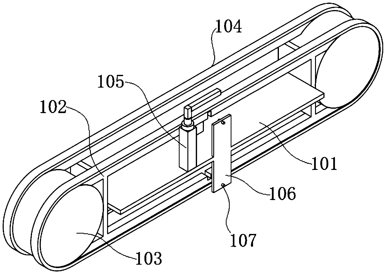
[0034] like Figure 3-5 As shown, the rotating frame 1 includes a fixed plate 101, a fixed frame 102, a driving wheel 103, a conveyor belt 104, a material retrieving platform 105, a positioning plate 106 and a photoelectric sensor 107, and the fixed plate 101 is arranged in the fixed frame 102. One surface of the fixed plate 101 is Connected with the reclaiming platform 105, the opposite sides of the fixed frame 102 are equipped with driving wheels 103, the sides of the fixed f...

Embodiment 2

[0043] see Figure 1-9 As shown, the present invention is a lens packaging device. Its working principle and usage method are as follows: several clamping seats 2 are evenly installed on the conveyor belt 104 of the rotating frame 1. Preferably, two surfaces of the clamping seats 2 are oppositely arranged The distance between the two pallets 202 is greater than the width of the driving wheel 103, and the surface of the conveyor belt 104 is provided with some limiting holes, the limiting holes and the clamping plates 202 are connected by pins, and the packaging box is a plastic box with a rotating cover;

[0044] When in use, when the clamping seat 2 moves to a designated position, the mask sheet 210 on the clamping seat 2 covers the photoelectric sensor 107, the clamping seat 2 stops, and the main lifting arm on the loading arm 3 rises at the same time, and the packaging One side of the box is in contact with the sliding baffle 204, and then the push rod is stretched to lift u...


PUM


Abstract

The invention discloses a lens packaging device, and relates to the technical field of lens processing. The lens packaging device comprises a rotating frame, clamping seats, feeding arms and materialguiding plates, the multiple clamping seats are connected and matched with the rotating frame, the feeding arms are matched with the clamping seats, the material guiding plates are arranged on one side of the rotating frame, and the material guiding plates are matched with the clamping seats. The feeding arms, the material guiding plates and a lens finished product assembly line are arranged on the periphery of the rotating frame, the packaging box is taken out of the feeding arm and opened through the clamping seat installed on the rotating frame, lenses are placed into a packaging box from the lens finished product assembly line, and finally the packaged lenses are sent out through the material guiding plate, so that full-automatic treatment is achieved, manual operation is avoided, thedefective product risk caused by the fact that fingers touch the lens surfaces is reduced, the product yield is increased, the labor cost is reduced, and the production efficiency is improved.

Description

technical field [0001] The invention belongs to the technical field of lens processing, in particular to a lens packaging device. Background technique [0002] Lens is a common optical device. A rough lens is obtained by smelting purified quartz or plasticizing resin, and then the lens is polished into a clear lens body. In addition, with the rise of cameras, some have functions Optically sensitive lenses are gradually being manufactured, including polarizers and filters. [0003] In the manufacturing process of these lenses, in order to prevent the surface of the lens from being scratched, the lens needs to be packaged after leaving the factory; at present, in order to prevent the lens from being scratched during the packaging process, the staff usually need to wear gloves to operate, although to a certain extent The problem of product yield reduction caused by grease and friction on the surface of the lens touched by fingers has been reduced, but it is still unable to eff...

Claims


Application Information

Patent Timeline
Patent Type & Authority Applications(China)
IPC IPC(8): B65B35/16
CPCB65B35/16
Inventor 刘迎春沈锦辉
Owner 东莞旭和光电科技有限公司
Why Eureka
Try Eureka