Electromagnetic cable guiding device
An electromagnetic and lead wire technology, applied in the direction of optical fiber/cable installation, etc., can solve the problems of complex operation, low construction efficiency, and short lead cable distance
Inactive Publication Date: 2012-09-05
成都鑫三洋科技发展有限公司
View PDF3 Cites 9 Cited by
- Summary
- Abstract
- Description
- Claims
- Application Information
AI Technical Summary
Problems solved by technology
But it also has some disadvantages: the cost of the optical cable protection tube is high, the operation is complicated and expensive during construction, the lead cable distance is short, and the construction efficiency is low.
Method used
View moreImage
Smart ImageViewing Examples

Examples
Embodiment
[0029] In a lead cable operation, the inner diameter of the optical cable protection pipe is 33mm, the outer diameter of the optical cable protection pipe is 38mm, the diameter of the optical fiber cable is 14mm, the distance of the lead cable is 2000m, the continuous lead cable is about 2000 meters, and the lead cable speed is continuously adjustable. Speed up to 200 meters per minute.
Login to View More PUM
 Abstract
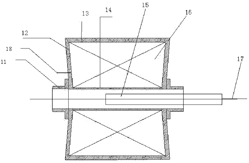
The invention discloses an electromagnetic cable guiding device, belonging to the field of building construction. The device comprises protection pipe guiders, coil baffles, a coil outer sheath, a coil inner sheath, an armature, a coil, an optical cable lead and a galvanization device, wherein the two protection pipe guiders are arranged on the two sides of the coil baffles at the two ends respectively, and one end of the coil inner sheath is sleeved outside; the coil inner sheath is wrapped by a coil; the two ends of the coil are located at the rear ends of the protection pipe guiders; the coil baffles are oppositely arranged on the coil inner sheath; the periphery of the coil is surrounded by the coil outer sheath; the coil is directly wound on the coil inner sheath; one end of the coil is led out from the end surface of the coil baffle to form a connection head which is connected with the external galvanization device of the electromagnetic cable guiding device; and the whole device is symmetric on the parallel tangent plane and vertical tangent plane of the coil inner sheath. According to the invention, the problems of complicated operation, high cost, short cable guiding distance, low construction efficiency and the like in the construction operation of the prior art are overcome at the same time.
Description
Technical field: [0001] The invention relates to the field of building construction, in particular to an electromagnetic lead cable device. Background technique: [0002] At present, it is a common construction method to introduce flexible cables such as cables into the guide channel of the protective pipe in construction, home decoration and other occasions. Optical fiber lead cable operation is an important process in the process of laying optical cables. At present, the more commonly used lead cable method In, there are the following ways: [0003] 1. Firstly, the steel wire with higher hardness is inserted into the protective tube, then the cable with weaker hardness is connected to the steel wire, and finally the steel wire is pulled out from the tube. At this time, the cable replaces the position of the steel wire and penetrates into the protective tube. In this method, because the protective tube and the steel wire are placed in coils, their axis is not an ideal stra...
Claims
Login to View More Application Information
Patent Timeline
 Patent Type & Authority Applications(China)
IPC IPC(8): G02B6/54
Inventor 曾维松
Owner 成都鑫三洋科技发展有限公司
Features
- Generate Ideas
- Intellectual Property
- Life Sciences
- Materials
- Tech Scout
- Unparalleled Data Quality
- Higher Quality Content
- 60% Fewer Hallucinations
Learn More Browse by: Latest US Patents, China's latest patents, Technical Efficacy Thesaurus, Application Domain, Technology Topic, Popular Technical Reports.
© 2025 PatSnap. All rights reserved.Legal|Privacy policy|Modern Slavery Act Transparency Statement|Sitemap|About US| Contact US: help@patsnap.com