
System and method for improving heat dissipation potential of heat sink

A technology of heat dissipation capacity and radiator, applied in the direction of heat exchanger type, indirect heat exchanger, heat exchange equipment, etc., can solve the problem of not optimizing the distribution of outer fins, not considering the distribution of the air inlet wind speed of the cooling fan, etc.

Inactive Publication Date: 2012-09-05
SHANGHAI SANY HEAVY IND
View PDF4 Cites 4 Cited by
  • Summary
  • Abstract
  • Description
  • Claims
  • Application Information

AI Technical Summary

Problems solved by technology

The deficiencies in this patent are as follows: 1) The air inlet velocity distribution of the cooling fan is not considered; 2) The distribution of the outer fins is uniform, and the distribution of the outer fins is not optimized

Method used


Image

  • System and method for improving heat dissipation potential of heat sink
  • System and method for improving heat dissipation potential of heat sink
  • System and method for improving heat dissipation potential of heat sink

Examples


Embodiment Construction

[0024] The present invention will be further described below in combination with principle diagrams and specific operation examples.

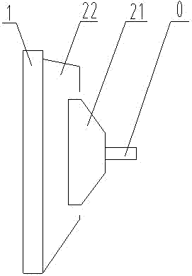
[0025] Such as figure 1 As shown, the system for improving the heat dissipation capacity of the radiator of the present invention includes a radiator assembly and a cooling fan 21, and the cooling fan 21 generates suction, so that the cold air used for heat dissipation passes through the radiator assembly. Preferably, the radiator assembly includes a radiator The core body 1 and the air guide cover 22, the air guide cover 22 is located between the radiator core body 1 and the cooling fan 21, the cooling fan 21 is connected to common driving components such as a motor through the fan shaft 0, under the action of the driving force, the fan shaft 0 drives the cooling fan 21 to rotate, and the external cold air then enters the air guide cover 22 and is finally introduced into the radiator core 1.

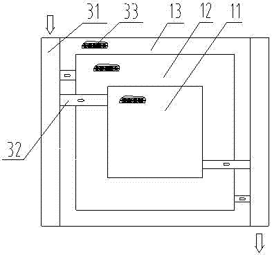
[0026] Radiator core 1 has several annular heat d...


PUM


Abstract

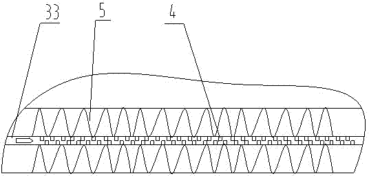
The invention discloses a system and a method for improving heat dissipation potential of a heat sink. The system comprises a heat sink assembly and a cooling fan, wherein the cooling fan is used for sucking cold air used for heat dissipation into the heat sink assembly, the heat sink assembly is divided into a heat sink core body and a wind scooper, the heat sink core body is provided with a plurality of annular heat dissipation regions, a runner pipeline is distributed on the heat sink core body, and the interior and the exterior of the runner pipeline in the annular heat dissipation regions are respectively provided with an inner fin and an outer fin. The system and method for improving heat dissipation potential of the heat sink disclosed by the invention fully utilize the wind speed distribution characteristic produced by a cooling fan, the heat sink is divided into N annular heat dissipation regions, heat dissipation design is independently carried out on each annular heat dissipation region, the most suitable inner fin and the most suitable outer fin are selected, and heat dissipation power in each heat dissipation region is guaranteed to be maximum at a designed wind speed.

Description

technical field [0001] The invention relates to the technical field of radiators for vehicles, in particular to a system and method for improving the heat dissipation capacity of radiators. Background technique [0002] At present, for radiators for engines, especially radiators for engineering machinery, the combination of cores can be divided into series, full parallel and series-parallel; the structure of radiators can be divided into plate-fin and tube strap style. To improve the heat dissipation performance of the radiator, the degree of turbulence inside the main flow pipe, the heat dissipation coefficient of the outer fins and its wind resistance, the cross-sectional shape of the flow pipe, and the thickness of each heat dissipation component are improved, without taking into account the cooling fan. The wind speed is distributed so that some areas of the radiator have a high heat dissipation coefficient, and some areas have a low heat dissipation coefficient. [00...

Claims


Application Information

Patent Timeline
Patent Type & Authority Applications(China)
IPC IPC(8): F28D1/053F28F1/42
Inventor 方明祥陶丕森
Owner SHANGHAI SANY HEAVY IND
Learn More