Bedside continuous hemodialysis filtration device
A hemodialysis and filtration technology, applied in the field of medical devices, can solve the problems of inability to remove medium and small molecule toxins at the same time, poor removal effect of medium molecule toxins, and large one-time investment of the whole machine, so as to remove water-soluble toxins, Simple structure and small one-time investment
- Summary
- Abstract
- Description
- Claims
- Application Information
AI Technical Summary
Problems solved by technology
Method used
Image
Examples
Embodiment 1
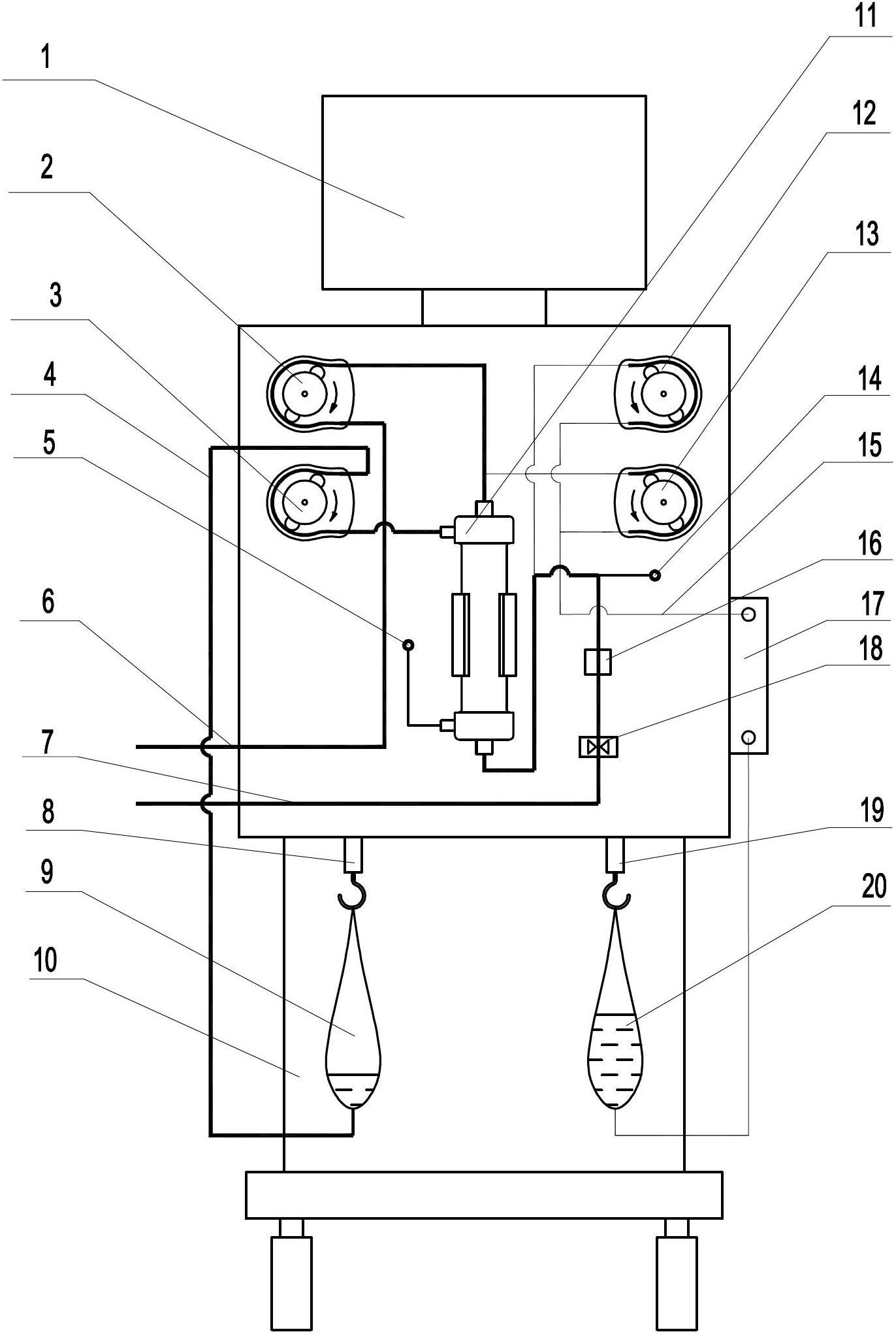
[0029] Such as figure 1 As shown, a display interface 1 is installed on the upper end of the cabinet 10. Four peristaltic pumps are installed on the upper part of the cabinet 10. These four peristaltic pumps are distributed in a rectangle. The upper left one is the first peristaltic pump 2, and the lower left one is the fourth peristaltic pump Of the pumps 3, the one on the upper right is the third peristaltic pump 12, and the one on the lower right is the second peristaltic pump 13. A hemodialyzer 11 is installed in the middle of the housing 10 , and the right side of the hemodialyzer 11 is equipped with a bubble detector 16 and a blocking clamp 18 , and the bubble detector 16 is located above the blocking clamp 18 . Below the hemodialyzer 11, a first electronic scale 19 and a second electronic scale 8 are arranged side by side, the first electronic scale 19 is located on the right side of the second electronic scale 8, and a fluid replacement bag 20 is suspended on the first...
Embodiment 2
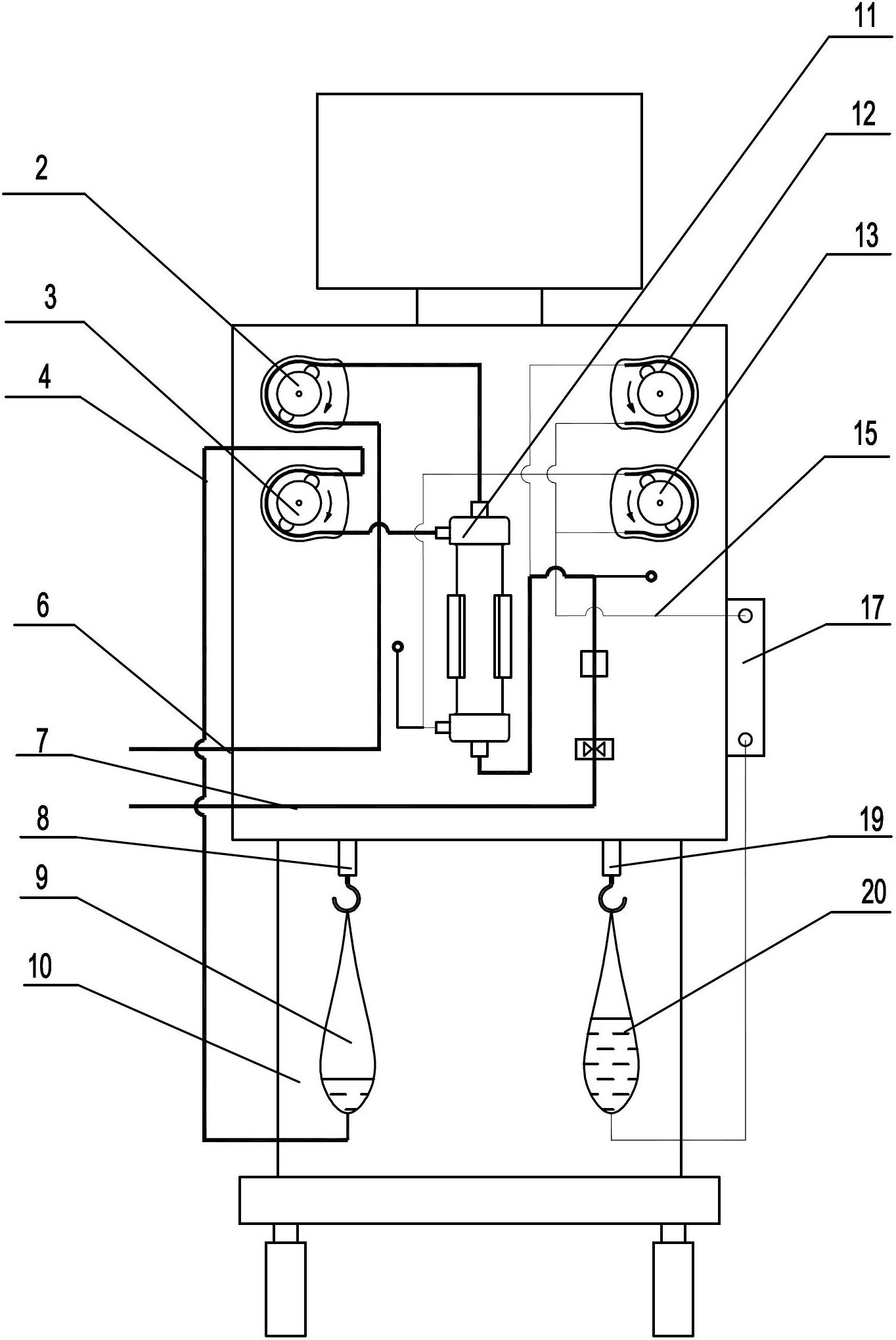
[0032] Such as figure 2 As shown, the fluid replacement circuit in this embodiment is as follows: one end of the fluid replacement pipeline 15 is connected to the fluid replacement bag 20, and the other end of the fluid replacement pipeline 15 passes through the heater 17 and is divided into two circuits, one of which bypasses the third peristaltic pump 12 Afterwards, it is connected with the venous line 7, and the other path bypasses the second peristaltic pump 13 and is connected with the outer membrane joint at the lower end of the hemodialyzer 11. The rest of the structure of this embodiment is the same as that of Embodiment 1, and will not be repeated here.
Embodiment 3
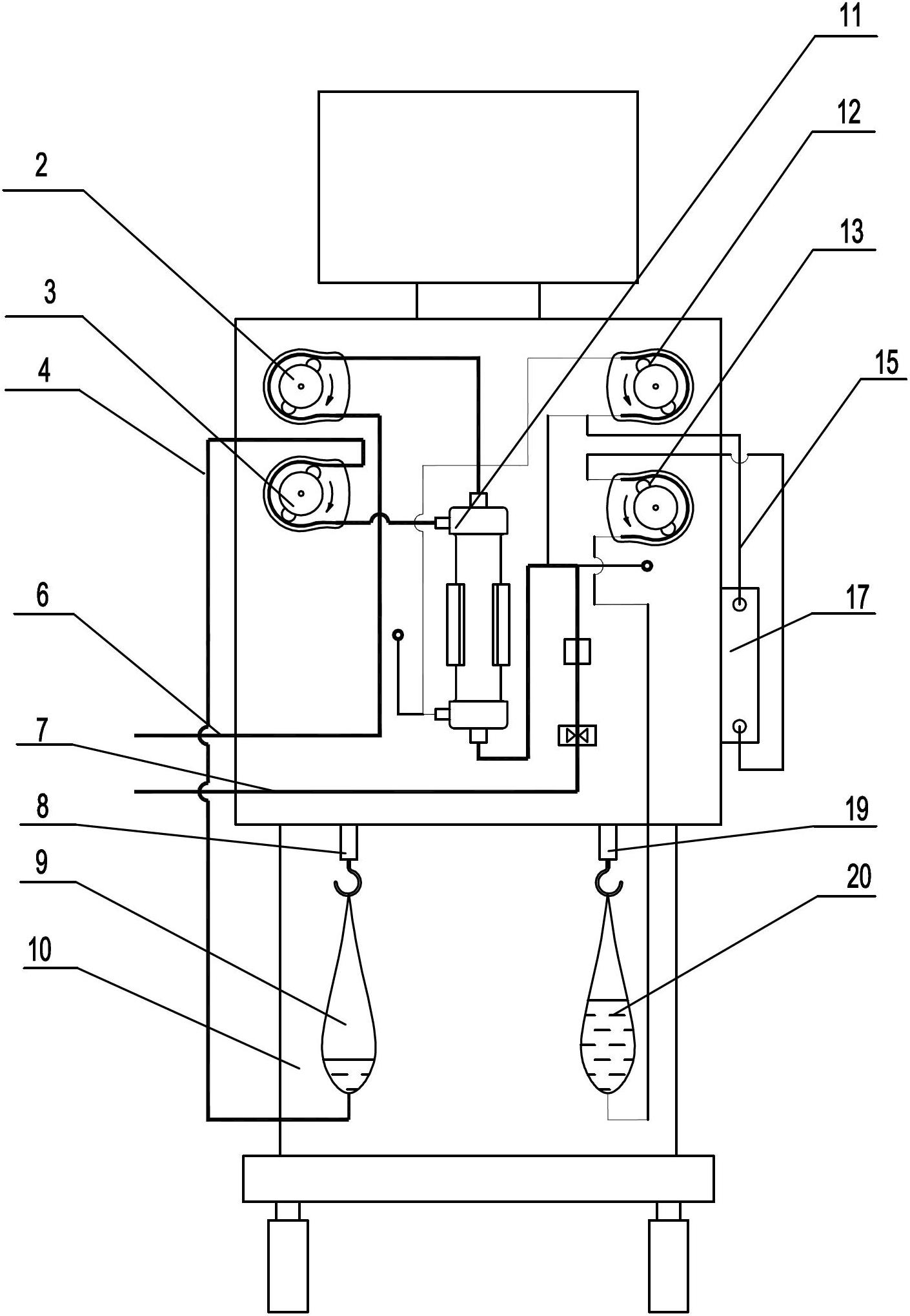
[0034] Such as image 3 As shown, the fluid replacement circuit in this embodiment is as follows: one end of the fluid replacement pipeline 15 is connected to the fluid replacement bag 20, and the other end of the fluid replacement pipeline 15 bypasses the second peristaltic pump 13 and then passes through the heater 17 and then divides into two circuits. One path is connected to the venous line 7, and the other path is connected to the outer membrane joint at the lower end of the hemodialyzer 11 after bypassing the rear 12 of the third peristaltic pump. The rest of the structure of this embodiment is the same as that of Embodiment 1, and will not be repeated here.
PUM
 Abstract
Description
Claims
Application Information
 - R&D
- Intellectual Property
- Life Sciences
- Materials
- Tech Scout
- Unparalleled Data Quality
- Higher Quality Content
- 60% Fewer Hallucinations
Browse by: Latest US Patents, China's latest patents, Technical Efficacy Thesaurus, Application Domain, Technology Topic, Popular Technical Reports.
© 2025 PatSnap. All rights reserved.Legal|Privacy policy|Modern Slavery Act Transparency Statement|Sitemap|About US| Contact US: help@patsnap.com


