Active gate bottom-edge device with function of adjusting water column pressure

A water column pressure, active technology, applied in water conservancy engineering, marine engineering, coastline protection, etc., can solve the problems of large opening and closing force and high cost

Active Publication Date: 2014-07-30
新疆金河水工机械设备有限公司
View PDF5 Cites 0 Cited by
  • Summary
  • Abstract
  • Description
  • Claims
  • Application Information

AI Technical Summary

Problems solved by technology

[0003] At present, the planar gates of the submerged hole prefer to adopt the water sealing form of the upstream panel and downstream water sealing when conditions permit. The advantage of this form is that the water column pressure on the top of the gate can be used instead of other forms of aggravation, thereby reducing the total cost of the gate. The bottom edge of this kind of gate is fixed, and the gate starts to bear the water column pressure at any position entering the orifice. When the gate falls to the bottom, the water column pressure bears the maximum. The matching hoisting equipment with larger capacity costs more

Method used


Image

  • Active gate bottom-edge device with function of adjusting water column pressure
  • Active gate bottom-edge device with function of adjusting water column pressure
  • Active gate bottom-edge device with function of adjusting water column pressure

Examples


Embodiment 1

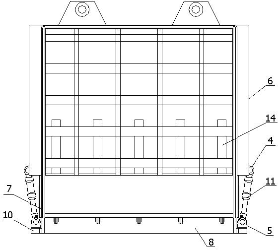
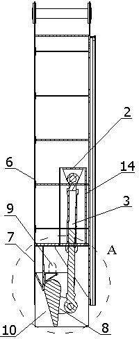
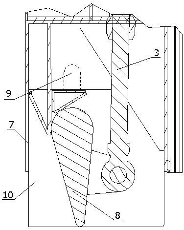
[0031] Such as figure 1 , 2 , 3, a device for actively adjusting the bottom edge of the water column pressure gate, including a rotating support 2, a rotating power mechanism 3, a first ear seat 4, a second ear seat 5, a door leaf 6, a bottom edge frame 7, a bottom Edge mechanism, slideway 9, bottom edge bracket 10 and vertical power mechanism 11, the bottom edge mechanism in this implementation is the bottom edge rotating mechanism 8, and described rotating support 2 is fixedly installed on the door leaf 6, and the rotating power mechanism 3. One end is hinged on the rotating support 2, and the other end of the rotating power mechanism 3 is hinged on the rotating side of the bottom edge rotating mechanism 8. The bottom edge frame 7 is fixedly installed on the bottom of the door leaf 6, and the bottom edge frame 7 is provided with a slide Road 9; the bottom edge bracket 10 is L-shaped, the side of the bottom edge bracket 10 is arranged between the bottom edge frame 7 and the ...

Embodiment 2

[0036] Such as Figure 4 , 5 , shown in 6 and 7, a kind of active adjustment water column pressure gate bottom edge device, comprises rotating support 2, rotating power mechanism 3, door leaf 6, bottom edge frame 7, bottom edge mechanism and vertical power mechanism 11, this The bottom edge mechanism in the embodiment is the bottom edge rotating mechanism 8, the rotating support 2 is fixedly installed on the door leaf 6, one end of the rotating power mechanism 3 is hinged on the rotating support 2, and the other end of the rotating power mechanism 3 is hinged on the bottom edge. On the rotating side of the edge turning mechanism 8, the bottom edge frame 7 is fixedly installed on the bottom of the door leaf 6, and the bottom edge frame 7 is provided with a shaft hole 12, and the fixed side of the bottom edge turning mechanism 8 passes through the shaft hole 12 through a hinge shaft. Hinged on the bottom edge frame 7; in this embodiment, the rotating power mechanism 3 is an oil...

Embodiment 3

[0039] Such as Figure 4 , 5 , 8 and 9, a device for actively adjusting the bottom edge of the water column pressure gate, including a rotating support 2, a rotating power mechanism 3, a door leaf 6, a bottom edge frame 7, a bottom edge mechanism and an elastic mechanism 13, the present embodiment The bottom edge mechanism is the bottom edge rotating mechanism 8, the rotating support 2 is fixedly installed on the door leaf 6, one end of the rotating power mechanism 3 is hinged on the rotating support 2, and the other end of the rotating power mechanism 3 is hinged on the bottom edge to rotate On the rotating side of the mechanism 8, the bottom edge frame 7 is fixedly installed on the bottom of the door leaf 6, and the bottom edge frame 7 is provided with a shaft hole 12, and the fixed side of the bottom edge rotating mechanism 8 is hinged through the shaft hole 12 through the hinge shaft. On the bottom edge frame 7; in the present embodiment, the rotating power mechanism 3 is...


PUM


Abstract

The invention relates to the field of water conservancy machinery, in particular to a gate bottom-edge device, namely an active gate bottom-edge device with a function of adjusting water column pressure, which comprises a rotating support, a rotating power mechanism, a gate leaf, a bottom-edge frame and a bottom-edge mechanism. The rotating support is fixedly mounted on the gate leaf. One end of the rotating power mechanism is hinged to the rotating support, and the other end of the rotating power mechanism is hinged to the bottom-edge mechanism. The bottom-edge frame is fixedly mounted at the bottom of the gate leaf. The bottom-edge mechanism is disposed on the bottom-edge frame through a hinge shaft. The bottom-edge mechanism on the gate is controlled to move up and down and rotate or move back and forth through the independent auxiliary power mechanism of the gate bottom-edge device, the rotatable bottom edge is turned back and forth to adjust the water position at the tail end of the bottom edge in contact with water flow, and accordingly resultant force required by the gate in operation is adjusted, closing force required by the gate is increased to the maximum extent, holding force and opening force required by the gate are increased, and finally capacity of a hoist is reduced.

Description

technical field [0001] The invention relates to the field of water conservancy machinery, in particular to a gate bottom edge device. Background technique [0002] A gate is a movable mechanism used to close, open or partially open a water orifice in a hydraulic structure. Its main function is to control the water level and regulate the flow. The gate is an important part of the hydraulic structure. Its safety and applicability affect the operation effect of the entire hydraulic structure to a large extent, and the opening and closing force required by the gate is an important part of the gate performance. [0003] At present, the planar gates of the submerged hole prefer to adopt the water sealing form of the upstream panel and downstream water sealing when conditions permit. The advantage of this form is that the water column pressure borne by the top of the gate is used instead of other forms of aggravation, thereby reducing the total cost of the gate. , the bottom edge...

Claims


Application Information

Patent Timeline
Patent Type & Authority Patents(China)
IPC IPC(8): E02B7/20
Inventor 邓旭林
Owner 新疆金河水工机械设备有限公司
Why Eureka
Try Eureka