Eureka AIR delivers breakthrough ideas for toughest innovation challenges, trusted by R&D personnel around the world.

Grain unloader conveyor tube with dribble control door

Inactive Publication Date: 2008-12-11
BLUE LEAF I P
View PDF15 Cites 14 Cited by
  • Summary
  • Abstract
  • Description
  • Claims
  • Application Information

AI Technical Summary

Benefits of technology

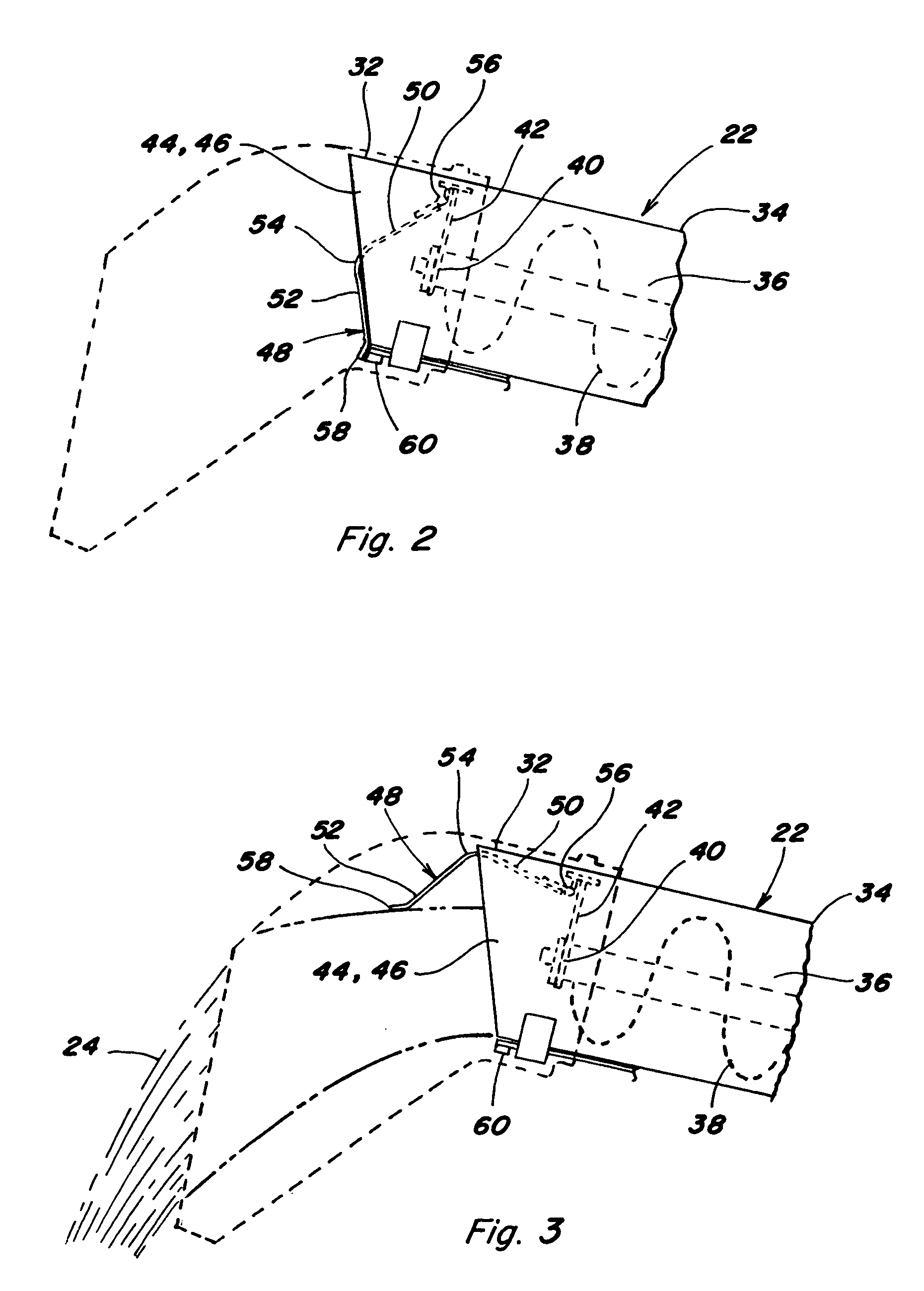
[0010]As an attendant advantage of the above construction, the center of gravity of the door is positioned such that at least a substantial portion of the weight of the door will act to urge the door toward the closed position, in contrast to the case wherein the door is pivoted at the bottom. This feature is advantageous alone, or in conjunction with a biasing element, for instance, but not limited to,

Problems solved by technology

A well-known problem associated with unloader conveyors of combine harvesters, is that grain that remains in the unloader conveyor tube after an unload cycle, can continue to dribble out of the discharge opening, as the unloader conveyor is swung to its transport position, and with the conveyor in the transport position, particularly as the harvester is moved over rough terrain, up hills, and the like.
However, an observed shortcoming of dribble doors such as this which are pivotable at the bottom, is that, absent some kind of powered actuator, grain pressure is required to maintain the door in the lowered position, and as the discharged grain flow tapers off, the spring force can prematurely lift the door so as to trap an undesirable amount of grain in the unloader tube.

Method used


Image

  • Grain unloader conveyor tube with dribble control door
  • Grain unloader conveyor tube with dribble control door
  • Grain unloader conveyor tube with dribble control door

Examples


Embodiment Construction

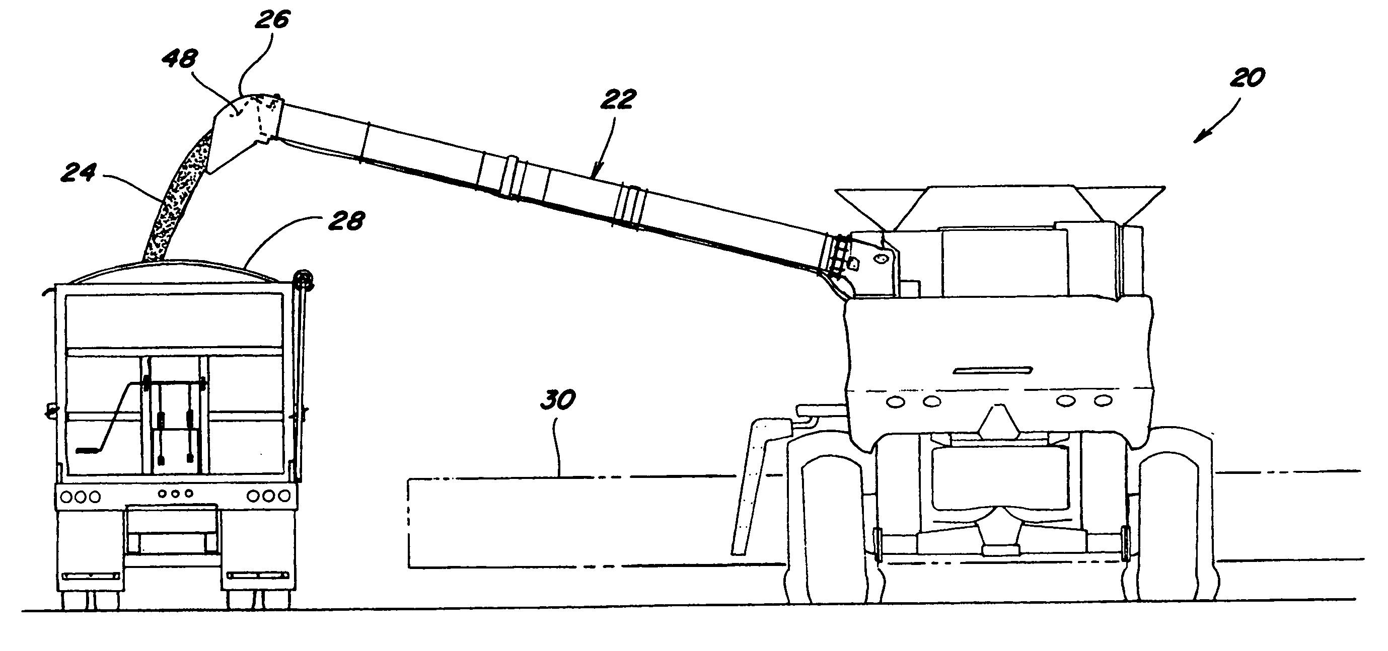
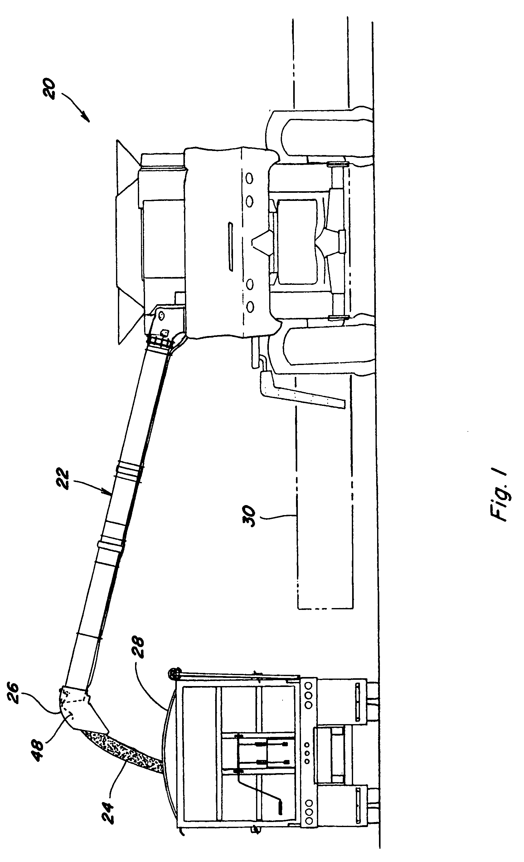
[0025]Referring now to FIG. 1, a combine harvester 20 is illustrated, including an unloader conveyor 22 transversely extending and deployed outwardly in an unloading position as it unloads grain 24 through a discharge boot 26 into a grain truck 28. This unloading operation can occur as harvester 20 and truck 28 are moving, which is referred to as unloading “on the go”, or stationary. At the end of the unloading operation, unloader conveyor 22 will be pivoted to a rearwardly directed transport position, extending along the adjacent side of harvester 20. It can be noted here, that truck 28 is located a substantial distance to the side of harvester 20, which is desired to avoid the possibility of contact with a header 30 mounted on the front of harvester 20, particularly when unloading on the go. It should also be noted that conveyor 22, when in the unloading position illustrated, will typically be tilted up toward the outer end thereof, at a greater angle, compared to when in the tran...


PUM


Abstract

Dribble control apparatus including a dribble control door hingedly or pivotally connected to an upper portion of a tube of a grain unloading conveyor. The door has a closed position covering a discharge opening of the tube for preventing grain dribbling, and an open position. The door has a shape which positions a center of gravity of the door for urging the door toward the closed position, including when closed, and which enables the door to support itself in the open position on a stream of grain flowing from the discharge opening with at least a substantial portion of the door spaced above the grain stream, while influencing or controlling an outward extent and direction of the flow of the stream.

Description

[0001]This application claims the benefit of U.S. Provisional Application No. 60 / 933,697, filed Jun. 7, 2007.TECHNICAL FIELD[0002]The present invention relates to a dribble door for the discharge opening of a grain unloader conveyor tube of a combine harvester, and more particularly, a dribble door configured so as to be supportable on a stream of grain discharged through a discharge opening of the conveyor while only minimally contacting the grain stream to influence or control the extent and direction of outflow of at least a portion of the stream, and which is shaped and oriented so as to be urged by its center of gravity toward a closed position covering at least the lower portion of the discharge opening, for preventing dribble.BACKGROUND ART[0003]U.S. Provisional Application No. 60 / 933,697, filed Jun. 7, 2007, is hereby incorporated by reference in its entirety.[0004]During an unload cycle for a combine harvester, the unloader conveyor (typically a helical auger) is operated t...

Claims


Application Information

Patent Timeline
IPC IPC(8): A01F12/60
CPCA01D41/1217
Inventor GROTELUESCHEN, NATHAN C.BANKS, JR., CLAYTON E.HORST, ANDREW J.
Owner BLUE LEAF I P
Why Eureka
Eureka Blog
Learn More