Numerical control slot milling machine for processing copper tailstock of optical fiber connector

A technology of CNC slot milling machine and optical fiber connector, which is applied in metal processing mechanical parts, metal processing, metal processing equipment and other directions, can solve the problem of affecting the use of optical fiber lines and cables, the connection of optical fiber wires is not in place, and the processing speed of manual operation is slow. and other problems, to achieve the effect of reducing human input, improving efficiency and high degree of automation

Inactive Publication Date: 2012-08-15
HANGZHOU GUANHE MACHINERY MFG
View PDF15 Cites 6 Cited by
  • Summary
  • Abstract
  • Description
  • Claims
  • Application Information

AI Technical Summary

Problems solved by technology

[0006] Existing milling machines for copper tailstock rely on manual operation or semi-mechanical operation, which has the following disadvantages: First, the copper tailstock is small in size as a workpiece, and manual operation will cause symmetrical and angular deviations in the four slots of the copper tailstock , high and low deviation and size deviation, etc., or cause the optical fiber connector to connect the optical line and cable, the connection between the optical fiber wires is not in place, which affects the use of optical fiber lines and cables; the second is the slow processing speed of manual operation and the production efficiency. Low; third, in the process of using a semi-mechanical milling machine, it is necessary to loosen and clamp the copper tailstock on the processing fixture four times by hand. Angle deviations are prone to occur during the manual loosening and tightening process, which affects processing precision

Method used


Image

  • Numerical control slot milling machine for processing copper tailstock of optical fiber connector
  • Numerical control slot milling machine for processing copper tailstock of optical fiber connector
  • Numerical control slot milling machine for processing copper tailstock of optical fiber connector

Examples


Embodiment Construction

[0049] The present invention will be further described in detail below in conjunction with the accompanying drawings and examples. The following examples are explanations of the present invention and the present invention is not limited to the following examples.

[0050] Example.

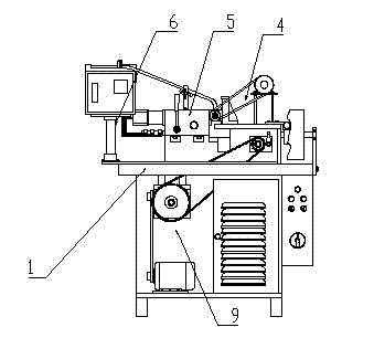
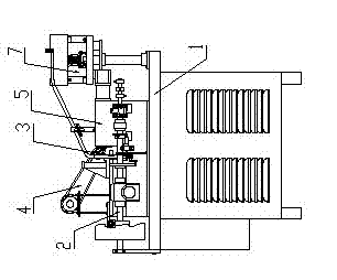
[0051] see Figure 1-Figure 29 , the CNC milling machine for processing the copper tailstock of the optical fiber connector in the present embodiment includes a frame 1, a main shaft 2, a manipulator mechanism 3, a tool mechanism 4, a clamp mechanism 5, a numerical control sensor mechanism 6, and a feeding mechanism 7 , transmission mechanism 8 and power mechanism 9. The manipulator mechanism 3 cooperates with the feeding mechanism 7, the manipulator mechanism 3 cooperates with the clamp mechanism 5, the tool mechanism 4 cooperates with the clamp mechanism 5, and the numerical control sensing mechanism 6 cooperates with the clamp mechanism 5.

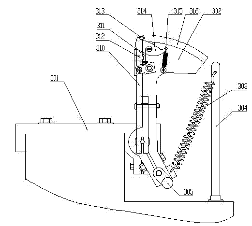
[0052] Manipulator mechanism 3 comprises manipulator...


PUM


Abstract

The invention relates to a numerical control slot milling machine for processing a copper tailstock. The slot milling machine comprises a rack, a main shaft, a feed mechanism, a mechanical arm mechanism, a clamp mechanism, a cutter mechanism, a power mechanism, a transmission mechanism and a numerical control sense mechanism, wherein the feed mechanism, the mechanical arm mechanism, the clamp mechanism, the cutter mechanism, the power mechanism, the transmission mechanism and the numerical control sense mechanism are installed on the rack; the power mechanism is connected with the transmission mechanism; the numerical control sense mechanism is connected with main shaft; and the cutter mechanism is connected with the main shaft. The numerical control slot milling machine for processing the copper tailstock is characterized in that the mechanical arm mechanism comprises a mechanical arm base, an oscillating bar, a chuck, a chuck spring, a bend board, a connecting rod, a shaft base, a push rod device, a cam device, a cullis, a scraping wing, a fixed rod, an oscillating bar spring, a connecting sliding column and an oscillating bar. The numerical control slot milling machine for processing the copper tailstock is high in automation degree, high in work efficiency, high in slot milling precision and high in slot milling speed.

Description

technical field [0001] The invention relates to a groove milling machine, in particular to a numerically controlled groove milling machine for processing copper tailstocks. The groove milling machine is used for processing copper tailstocks of optical fiber connectors and belongs to the field of mechanical processing. Background technique [0002] A Chinese utility model patent, the patent name is slot milling machine, the publication number is CN2593989Y, discloses a slot milling machine, which includes a machine table, the two sides of the machine table are equipped with a clamping structure that can clamp the processed object, A slot milling mechanism and a power structure for reciprocating movement of the linked slot milling mechanism are installed between the clamping structures; the slot milling mechanism has several sliding seats that can be adjusted for angles and is assembled on the sliding seats to independently adjust its front, rear, The milling cutter group at t...

Claims


Application Information

Patent Timeline
Patent Type & Authority Applications(China)
IPC IPC(8): B23C3/28B23Q7/00B23Q7/04B23Q1/25B23Q5/10B23B31/20
Inventor 程启富
Owner HANGZHOU GUANHE MACHINERY MFG
Why Eureka
Try Eureka