Isolating switch

A technology of isolating switches and static contacts, which is applied in the direction of air switch components, etc., can solve the problems of uneven distribution of electric field and poor safety, and achieve the effect of solving uneven distribution of electric field, simplifying the operation process and improving safety performance

Inactive Publication Date: 2012-08-08
SUZHOU LONGER ELECTRIC CO LTD
View PDF6 Cites 2 Cited by
  • Summary
  • Abstract
  • Description
  • Claims
  • Application Information

AI Technical Summary

Problems solved by technology

[0004] In view of the above-mentioned defects in the prior art, the purpose of the present invention is to propose a disconnector that solves the problems of uneven electric field distribution and poor safety while simplifying the operation

Method used


Image

  • Isolating switch
  • Isolating switch
  • Isolating switch

Examples


Embodiment Construction

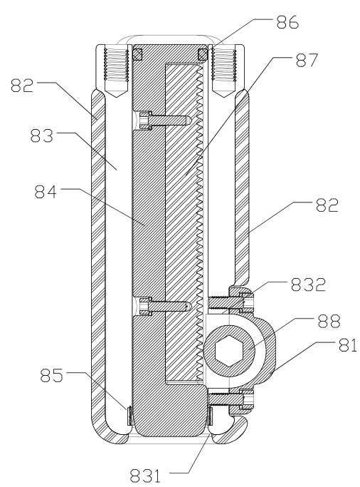
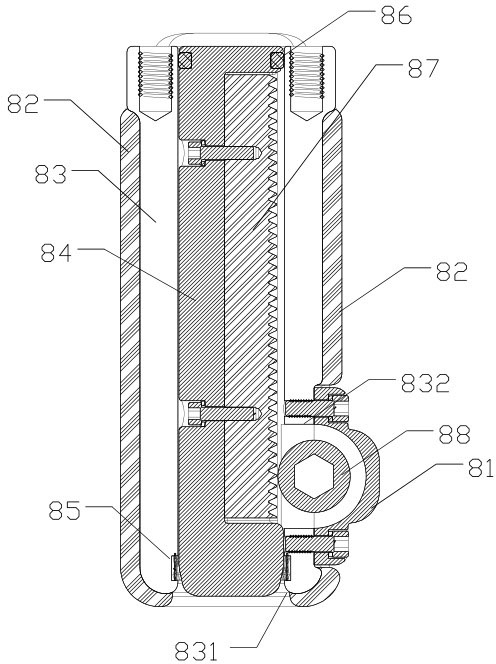
[0013] Such as figure 2 Shown is a schematic cross-sectional view of a preferred embodiment of the isolating switch of the present invention. The isolating switch is mainly composed of a static contact 83 and a moving contact 84 . It can be seen from the figure that the static contact 83 is a hollow cylinder with an opening 831 at one end, and a hole 832 penetrating into the inner cavity of the static contact is provided on the side wall near the end of the opening 831, and the static contact The outer surface of 83 is provided with an epoxy resin sealing layer 82; in addition, a watch strap contact finger 85 is provided on the inner side of the static contact near the opening.

[0014] Looking at the moving contact 84 again, it is a block structure matched with the inner cavity of the static contact, and is compatible with sliding in the inner cavity of the static contact. From the perspective of the length direction, the movable contact can be formally divided into three ...


PUM


Abstract

The invention discloses an isolating switch. The insolating switch comprises a fixed contact and a moving contact, wherein the fixed contact is a hollow cylinder with an opening at one end, a hole which penetrates into an inner cavity of the fixed contact is arranged on the side wall at one end which is near the opening, and the fixed contact is coated with a fixing sealing epoxy resin layer; and the inner cavity of the fixed contact and an inner cavity of the moving contact are matched with each other and are compatible in a sliding mode in the inner cavity of the fixed contact, the moving contact is provided with a guide portion, a recessed portion and a contact portion in a length direction, the moving contact is electrically connected with the fixed contact through a watchband contact finger and a tooth-shaped transmission assembly is arranged between the recessed portion and the hole. The isolating switch uses the fixing sealing epoxy resin layer to effectively solve the problem of unevenness of electric field distribution, and the safety performance of the isolating switch is improved; and simultaneously, the operation process is simplified and the electric isolation efficiency is improved through direct-acting control of the tooth-shaped transmission assembly.

Description

technical field [0001] The invention relates to a high-voltage air circuit breaker, in particular to a direct-acting on / off isolating switch. Background technique [0002] The disconnect switch is a mechanical switch device that can provide electrical isolation breaks in accordance with the specified requirements in the open position. The so-called electrical isolation means that there is no direct electrical connection between the two circuits. That is, the two circuits are insulated from each other. When the internal insulation of the switch body is damaged due to line aging or air leakage, the isolation fracture provided by the isolation switch must ensure that the fracture will not be broken down in the air and cause discharge. Such as figure 1 Shown is a structural schematic diagram of a commonly used isolating switch. The application of the isolating switch is usually at the voltage level of 35kV and below. It is installed in three phases and uses up and down (vert...

Claims


Application Information

Patent Timeline
Patent Type & Authority Applications(China)
IPC IPC(8): H01H31/02
Inventor 袁忠赵超董强华
Owner SUZHOU LONGER ELECTRIC CO LTD
Why Eureka
Try Eureka