Preparation method for grapheme hydrogen storage electrode
A graphene and electrode technology, which is applied in the field of nanomaterial preparation, can solve the problems of high price, harsh conditions, and poor stability, and achieve the effects of low cost, simple preparation process, and increased specific surface area
- Summary
- Abstract
- Description
- Claims
- Application Information
AI Technical Summary
Problems solved by technology
Method used
Image
Examples
Embodiment 1
[0022] In the reaction chamber of the automatic control DC arc hydrogen plasma equipment, the pure graphite block is used as the anode, the pure carbon rod is used as the cathode, and the distance between the two electrodes is 20 mm. 2 , the discharge voltage is 40V, and the discharge current is 90A. A graphene hydrogen storage material is prepared. After the graphene material and the binder PVDF are mixed at a mass ratio of 1:1 to 7:1, after comparing the combination of the mixed sample and the matrix nickel foam, the optimal mixing ratio is determined to be 4:1. This graphene material is made into an electrode sheet as a working electrode, Ni(OH) 2 The / NiOOH electrode is used as the auxiliary electrode, the calomel electrode is used as the reference electrode, and the electrolyte is 6mol / L saturated KOH solution. After the simulated battery is composed, the electrochemical performance is tested.
Embodiment 2
[0024] After vacuuming, 0.05MPa of H 2 , the discharge voltage is 40V, and the discharge current is 90A. A graphene hydrogen storage material is prepared. After the graphene material and the binder PVDF are mixed at a mass ratio of 4:1, the graphene material is made into an electrode sheet as a working electrode, and Ni(OH) 2 The / NiOOH electrode is used as the auxiliary electrode, the calomel electrode is used as the reference electrode, and the electrolyte is 6mol / L saturated KOH solution. After the simulated battery is composed, the electrochemical performance is tested. Other experimental conditions are the same as in Example 1, except that the distance between the two poles is 10mm, and the H 2 is 0.05MPa.
Embodiment 3
[0026] Other experimental conditions are identical with embodiment 1, and difference is: the distance between two poles reaches 30mm, the H 2 is 0.07MPa.
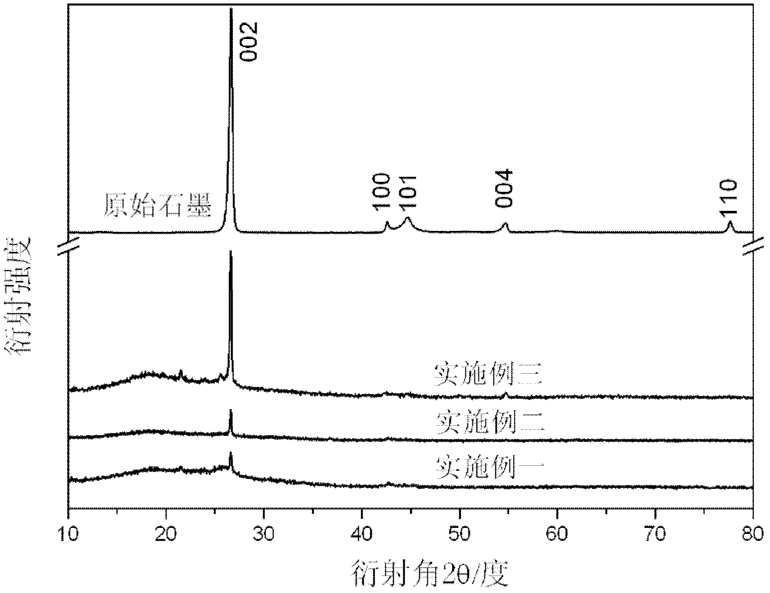
[0027] figure 1 It is the X-ray diffraction (XRD) collection of patterns of the graphene material synthesized according to embodiment one, embodiment two, embodiment three. The XRD pattern shows that the graphene sample has an obvious broadening peak in the range of 20-30°, indicating that it is a disordered state. The appearance of the (002) peak indicates that the prepared graphene is a multilayer sheet structure.
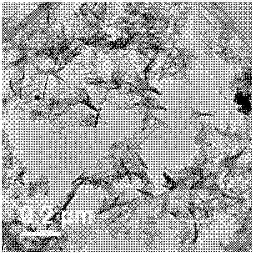
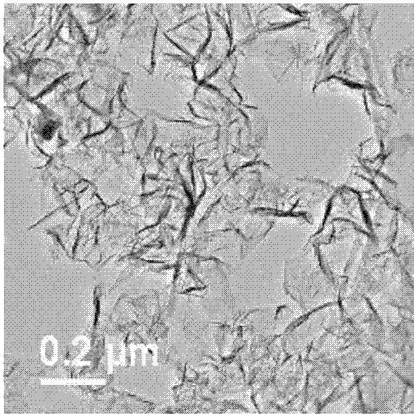
[0028] Fig. 2 (a), (b), (c) are the transmission electron microscope (TEM) figure of the graphene material synthesized according to embodiment one, embodiment two, embodiment three respectively. TEM images (a), (b) and (c) show that the graphene layer spacing prepared in Example 1 is relatively small, and its size is about 0.2 μm. However, the distance between graphene sheets prepared in Example 2 and Exam...
PUM
 Abstract
Description
Claims
Application Information
 - R&D
- Intellectual Property
- Life Sciences
- Materials
- Tech Scout
- Unparalleled Data Quality
- Higher Quality Content
- 60% Fewer Hallucinations
Browse by: Latest US Patents, China's latest patents, Technical Efficacy Thesaurus, Application Domain, Technology Topic, Popular Technical Reports.
© 2025 PatSnap. All rights reserved.Legal|Privacy policy|Modern Slavery Act Transparency Statement|Sitemap|About US| Contact US: help@patsnap.com


