
Axial-flow pump for particle image velocimetry and particle image velocimetry method

A particle image velocimetry and axial flow pump technology, which is applied to components of pumping devices for elastic fluids, axial flow pumps, pumps, etc., can solve the problems of increased processing costs, complex structures, and very different structural forms Long distance and other problems to achieve the effect of improving measurement accuracy and service life

Inactive Publication Date: 2012-08-01
JIANGSU UNIV
View PDF5 Cites 16 Cited by
  • Summary
  • Abstract
  • Description
  • Claims
  • Application Information

AI Technical Summary

Problems solved by technology

At present, the traditional axial flow pump for PIV measurement has the following characteristics: (1) In order to fix the pump shaft, it is necessary to redesign a pair of straight guide vanes before the impeller inlet, resulting in the wake of the water trace behind the straight guide vanes making the water flow at the impeller inlet uneven; (2) install a transparent circular runner chamber behind the straight guide vane, and surround a transparent plexiglass cuboid small water tank outside the runner chamber, the structure is complex, which increases the processing cost; (3) for After simulating the rear guide vane hub, there is a stainless steel pipe behind the impeller hub, which is different from the real axial flow pump structure
(4) Only the impeller runner chamber is made as a transparent structure. The structure of the test pump is the same as that of the traditional axial flow pump, and no structural innovation has been found.
[0004] After searching, in terms of pumps for PIV measurement, the invention patent application of Jiangsu University "a centrifugal pump for three-dimensional PIV measurement" (application number: 201010520430), the common point of the two inventions is that they are both for PIV measurement pumps, but the research objects belong to centrifugal pumps and axial flow pumps respectively. Centrifugal pumps and axial flow pumps are two completely different vane pumps, which are very different in terms of occasions and structural forms.

Method used


Image

  • Axial-flow pump for particle image velocimetry and particle image velocimetry method
  • Axial-flow pump for particle image velocimetry and particle image velocimetry method
  • Axial-flow pump for particle image velocimetry and particle image velocimetry method

Examples


Embodiment Construction

[0019] The technical solution of the present invention will be described in detail below in conjunction with the accompanying drawings.

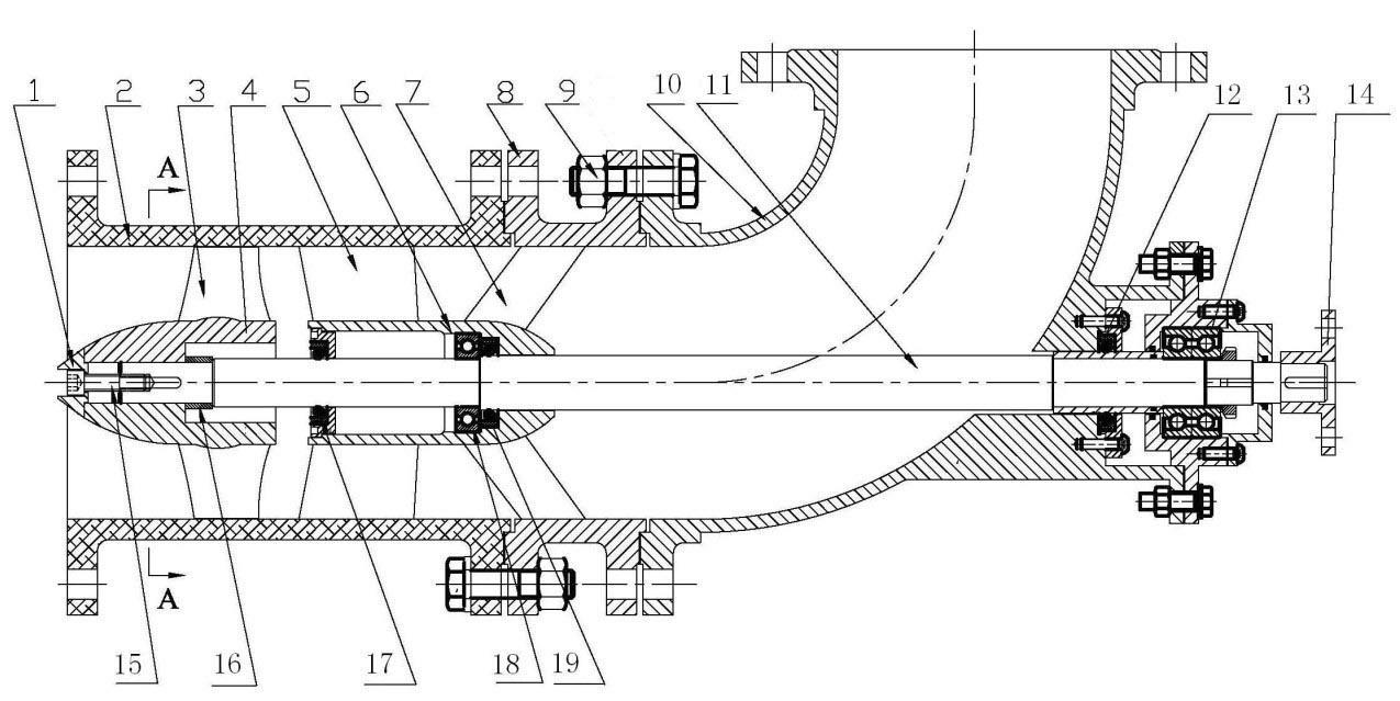
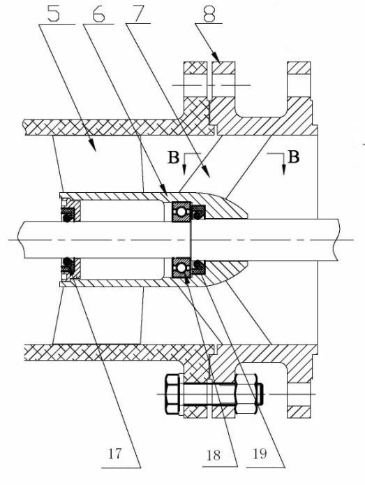
[0020] exist figure 1 and figure 2 Among them, the axial flow pump consists of water guide cone 1, impeller blade 3, impeller hub 4, guide vane blade 5, guide vane hub 6, transparent square plexiglass cylinder 2, streamlined rib 7, flange 8, bolt 9, pump Shaft 11, elbow section 10, deep groove ball bearing A13, deep groove ball bearing B18, screw 15, shaft sleeve 16, oil seal A12, oil seal B17, oil seal C19 and coupling 14 and other parts. The impeller blade 3 and the impeller hub 4 are welded and fixed to form an impeller, and the guide vane 5 and the guide vane hub 6 are welded and fixed to form a guide vane. Both the impeller and the guide vane are inside the transparent plexiglass tube; The radial gap between the edge and the transparent square plexiglass cylinder 2 is 0.5mm. When the impeller rotates with the pump shaft 11, the impel...


PUM


Abstract

The invention discloses a novel axial-flow pump for particle image velocimetry, which is mainly used for velocity field measurement of the internal flow of the axial-flow pump. The axial-flow pump comprises a water-guide cone, an impeller blade, an impeller hub, an impeller guide blade, an impeller guide hub, a square organic glass outer barrel, a streamline ribbed plate, a guide vane body flange, a bolt, a shaft, a bending tube section, a bearing, screws, a shaft sleeve, an oil seal, a rolling bearing, a coupler and other parts. The novel axial-flow pump has the beneficial effects of improving the accuracy of particle image velocimetry (PIV) of the axial-flow pump, innovating the structure of the novel axial-flow pump, realizing particle image velocimetry in the real flow field in the axial-flow pump, prolonging the service life of the novel axial-flow pump for particle image velocimetry, leading the flow field of the axial-flow pump used for an experiment to be more similar to that of a real product pump, and ensuring the real flow in an impeller and a guide vane to be observed and measured at the same time.

Description

technical field [0001] The invention relates to an axial flow pump for particle image velocity measurement and a velocity measurement method thereof, which is mainly used for velocity field measurement of flow inside an axial flow pump impeller and a guide vane. Background technique [0002] Particle Image Velocimetry (hereinafter referred to as PIV) technology is a new type of flow velocity measurement technology developed on the basis of flow field display technology in recent years. The camera continuously takes two photos of the tracer particles displayed on the light source surface of the sheet, and obtains the direction and size of the flow field velocity according to the displacement difference and time difference of the tracer particles on the two photos. Because PIV measurement technology can not only overcome the limitation of single-point measurement of flow field, but also perform instantaneous and non-contact measurement of the whole flow field, it is widely use...

Claims


Application Information

Patent Timeline
Patent Type & Authority Applications(China)
IPC IPC(8): F04D3/00F04D29/52F04D29/04G01P5/20
Inventor 张德胜王川张华施卫东
Owner JIANGSU UNIV
Learn More